Playing Video On An 8-bit Microcontroller

The LCD displays for Nokia phones have seen a ton of use as easily interfaced displays for Arduino or other microcontroller projects. Usually, these LCDs are only used for displaying a few lines of text, or if someone is feeling really fancy, a small graph. Shame, then that we don’t see more complicated and computationally difficult tasks like playing video very often. [Vinod] sent us his way of playing video on these small color screens, surprisingly using only an ATMega32 microprocessor.

The build started off by saving uncompressed image data on an SD card using code from a previous project. [Vinod] was able to write a slideshow program to go through the SD card one file at a time and displaying each image. From there, it was simply a matter of using a Python script to convert frames of an .AVI video file to an uncompressed image and display them at 15 frames/second.

Turning these videos into talkies was a bit of a problem, but after taking an uncompressed .WAV file and sending that to a PWM pin on the ATMega, [Vinod] managed to play sound alongside his video.

The result is the ability to play a video with sound at 15 frames a second and a 132 x 65 resolution. You can check out the demo video after the break.

Continue reading “Playing Video On An 8-bit Microcontroller”

Making An Audio Spectrum Analyzer With A Microcontroller

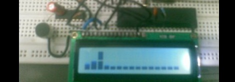
While [Vinod] says he’s not an expert in this sort of thing, we really like his audio spectrum analyzer build from a simple microcontroller and LCD display.

It is a well-studied fact that every audio waveform – a recording of your voice, for instance – is just the sum of many, many sine waves. These sine waves can be plucked out using Fourier analysis, using a Discrete Fourier transform. This is the principle that spectrum analyzers operate under; [Vinod] wrote a bit of code using DFT to take apart audio captured from a microphone and output their frequency on an LCD display.

To output the spectrum on his LCD, [Vinod] stacked horizontal bars up into 8 custom characters in his display. Like [Vinod]’s previous audio on an ATMega32 experiment, an LM324 amplifier is connected to the ATMega through an analog pin. [Vinod] has a very clever build on his hands with his spectrum analyzer, and a great answer to the perennial ‘how do I build a guitar tuner’ questions we’re constantly asked.

After the break, you can see [Vinod]’s spectrum analyzer in action. Be forewarned; you may want to turn down the volume.

Continue reading “Making An Audio Spectrum Analyzer With A Microcontroller”

Making A Digital Delay From A Simple Microcontroller

If you’d like to start experimenting in DSP, or just want to build a guitar pedal, here’s the project for you. It’s an audio echo using just a microcontroller from the fruitful workshop of [Vinod].

For his circuit, [Vinod] fed the output of a small electret microphone into a small amplifier, and then into the ADC of an ATMega32. Inside the microcontroller, [Vinod] set up a circular array which writes the voltage from the microphone and sends it out to a speaker. Because the array is circular (i.e. it loops around when it gets to the end), [Vinod] has a digital version of a loop of magnetic tape, perfect for recording sounds and playing back echos.

Because [Vinod] is using an ATMega32, he only has a limited amount of RAM to record audio samples. The delay time could be lengthened with a more capable microcontroller, or even the addition of a large RAM chip. With his setup, [Vinod] can do some really interesting experiments with audio and DSP, so we wouldn’t be surprised if an enterprising musician used this project as the basis for a digital delay stomp box.

You can check out [Vinod]’s demo of his echo machine after the break.

Continue reading “Making A Digital Delay From A Simple Microcontroller”

Experimenting With 8-bit Graphics

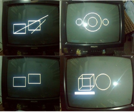
[Vinod] has done a lot of work with microcontrollers, but this is his first try at displaying graphics using composite video. He had a small PAL television on hand, and an ATmega32 which just needs a stable clock source and a few resistors to get things going.

There are a lot of other hacks around that use composite video out with microcontrollers. But this is a ground-up approach which will help you understand the concepts behind these graphics. [Vinod] started by calculating the possible resolution. He needs to hold a frame buffer in memory, and since his chip has just 2 kilobytes of SRAM this will be the limiting factor. He settled on a display area of 128 by 64 pixels. This divides evenly by 8 so he’s not wasting any bits, and it totals 1k, leaving half of the SRAM for use in calculating the shapes which populate the buffer. An interrupt service routine runs ever 64 microseconds to feed data for each line of the display.

With the scanning in place, he moved on to fill the frame buffer. Two functions are used, one which sets a pixel the other clears a pixel. He compares these to using a pencil and an eraser. By calling these functions from his main program he is able to draw lines, boxes, and circles. A bit of creative looping and he’ll have animations as well, but that’s a concept for a different post.

Putting Multitasking On An AVR

[vinod] wanted to familiarize himself with AVR assembly programming, but wanted to do something a little more ambitious than simply blinking an LED. While the completed build does blink a few LEDs, we love that e decided to implement multitasking on his microcontroller.

The program [vinod] came up with uses round robin scheduling to give one of the seven programmed tasks a little bit of compute time every time a timer is triggered. Although it’s extremely simple compared to “real-life” real-time operating systems like VxWorks, it’s still an impressive achievement.

In the video after the break, [vinod] shows off his task-switching with seven LEDs. The white LED is a PWM task, while the six other LEDs are simple toggling tasks  that switch a LED on and off at set intervals independent of each other. This would be hard – if not impossible – to do without some sort of scheduling. Nice work, [vinod].

Continue reading “Putting Multitasking On An AVR”

WAV Playback With An ATmega32

[Vinod Stanur] just finished another hobby project by building a WAV audio player using a microcontroller. He had started development a while back using a PIC microcontroller. But the chip he was using didn’t have enough SRAM to allocate as a playback buffer. When he got his hands on an ATmega32 his mind turned back to the project and he saw it through to the end.

He takes advantage of what he learned on several earlier builds. He’s using a TV remote as input, just like his Snake game did. Storage is provided by an MMC card, a trick he perfected with this voice recorder project. Instead of using a FAT library, he uses his own code to read the linked-list (File Allocation Table) for sector addresses, then he parses the WAV header and processes the file accordingly.

Playback uses two 512 byte buffers. One is feeding the output while the other is being populated from the memory card. When the output buffer is exhausted the two are swapped and the process continues. You’ll find [Vinod’s] demo of the project after the break.

Continue reading “WAV Playback With An ATmega32”

DIY Quadcopter For Around $200

We think [FlorianH] did a bang-up job of prototyping his Minima Quadcopter on the cheap. The total bill comes in right around $200 and we’re very happy with the quality of parts as well as the results.

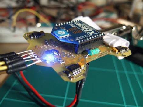
Here you can see the top of the double-sided board which he etched to host all of the components. At each corner there is a power MOSFET which drives the motor. At first glance we thought that the Xbee module was acting as the radio control and processer as well. But on the underside you’ll find an ATmega32 which is responsible for reading the Gyroscope sensor and Accelerometer, processing these signals and driving each MOSFET via PWM lines to provide stability.

You can see some flight tests after the break. [FlorianH] mentions that there is some oscillation in the feedback loop when both the gyro and accelerometer are used. But cut the accelerometer out of the equation and the platform is rock-solid.

This build uses carbon tubes to mount the motors, which we think will be a little more robust than the all-PCB designs are.

Continue reading “DIY Quadcopter For Around $200”