Hands Free Hot Air Station

In an effort to ease the process of soldering Ball Grid Array (BGA) chips at home [Roger] rigged up a hands-free solution for his hot air equipment.

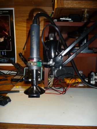
The main component in the build is an Aoyue hot air rework station that he already had in his workshop. He wanted an adjustable mount that would hold it steady when reflowing parts so he hit Amazon and bought a $14 articulated lamp. After ditching the funnel-shaped shade he bolted a cable clamp to the socket housing. This can be tightened on the hot air wand, with the spring tension of the lamp making it easy and quick to reposition the nozzle. [Roger] sent this project directly to our tips line and we’ve embedded the rest of the project images after the break.

If you’re looking for a more DIY rework solution you should checkout this hot air pencil hack. It uses a desoldering iron, a fish pump, and some metal mesh as a heat sink to put out a stream of very hot air.

Continue reading “Hands Free Hot Air Station”

BGA Soldering With A Paint Stripper And Stopwatch

Having just received a shiny set of PCBs from the fab-house [Devbisme] needed a way to solder the main chip in place. It has a Ball-Grid Array footprint which is notoriously difficult to populate in a home lab. But he makes it look pretty easy and decided to share a video tutorial of the process.

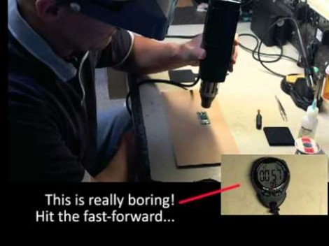
The main tool he used is the paint stripper (heat gun) seen above. Since he didn’t have his own fancy reflow oven he made things work with the gun as his heat source. First he applies a generous layer of liquid solder flux to the BGA footprint on the board. Next he melts some solder onto the tip of his iron and uses it to tin all of the board’s BGA pads. Then it’s time for the critical step of positioning the chip. He uses vacuum tweezers to set it in place, and traditional tweezers to fine-tune its position. From here he heats with the paint stripper for two minutes, starting far above the board and slowly moving closer, with the reverse at the end of the soldering process. Once cool the board is cleaned with distilled water and blown dry with compressed air. After a visual inspection he finishes the application with a 30 minute stay in a 300 degree oven. We’ve included the video after the break for your convenience.

We’ve seen a similar technique used for replacing a chip on an already populated board.

Continue reading “BGA Soldering With A Paint Stripper And Stopwatch”

Swapping Out Eee PC BGA Chip For 1.6 GHz Upgrade

Personally we find this Ball-Grid Array chip-swap rather horrifying. But if you want to beef up the processor on your 701 Eee PC this is what you’ll need to go through. Not only did [Red Fathom] upgrade to a 1.6 GHz chip, but he managed to get the computer to boot up with the new hardware in place.

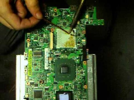
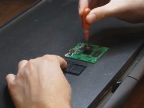
BGAs are notoriously hard to solder. This hack pulls it off using just a hot air gun. [Red Fathom] heats the board from the underside until the solder melts and he can pluck off the old chip. He then uses a solder braid and iron to remove extra solder from the footprint. After a little cleanup with a cotton swab and some flux he plops in an Intel Pentium M LV 778. It doesn’t look like he added any solder after the cleaning process. Perhaps he’s relying on the small amount left on the tinned pads of the board?

After the break you can see the soldering process and a video of the new processor booting Xandros.

Continue reading “Swapping Out Eee PC BGA Chip For 1.6 GHz Upgrade”

Know Thy Enemy: Open Vias In BGA Footprints

[Andrew Zonenberg] has crossed a line in his electronic hobby projects. The Ball Grid Array (BGA) is a type of chip footprint which most hobbyists leave to the professionals. But he’s learned the skills necessary to use them in his projects. Recently he ran a test batch to show off his soldering process and illustrate one of the errors a novice might make.

For those that are unfamiliar, the BGA footprint is notoriously difficult to accurately solder because it consists of a large grid of tiny points covering the bottom of the chip. There’s no way to get in there with an iron, so soldering depends on accurate placement of solder paste and chip, as well as a near-perfect reflow cycle. Often times it’s difficult for the professionals too. Many blame the heat-failure of Xbox 360 on the complications of the BGA connects for one of the console’s chips.

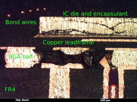
For this experiment [Andrew] wanted to show what happens if you include vias in the BGA footprint. It’s fine to do so, as long as they’re capped. But if a standard via is included, capillary action ends up pulling the solder down into the via instead of making a connection with the chip. The image above is a cross-section of one such uncapped via, seen on the far right.

[Thanks George]

Reworking Ball Grid Array Circuit Board Components At Home

[Jack Gassett] is developing a new breakout board for an FPGA. The chip comes in a ball grid array (BGA) package which is notoriously difficult to solder reliably. Since he’s still in development, the test boards are being assembled in his basement. Of the first lot of four boards, only one is functional. So he’s setting out to rework the bad boards and we came along for the ride.

To reflow the surface mount components he picked up a cheap pancake griddle. The first thing [Jack] does is to heat up the board for about two minutes, then pluck off the FPGA and the FTDI chips using a vacuum tweezers. Next, the board gets a good cleaning with the help of a flux pen, some solder wick, and a regular soldering iron. Once clean, he hits the pads with solder paste from a syringe and begins the soldering process. BGA packages and the solder paste itself usually have manufacturer recommended time and temperature guidelines. [Jack] is following these profiles using the griddle’s temperature controller knob and the timer on an Android phone. In the video after the break you can see that he adjusts the timing based on gut reaction to what is going on with the solder. After cleaning up some solder bridges on the FTDI chip he tested it again and it works!

Continue reading “Reworking Ball Grid Array Circuit Board Components At Home”

Reverse Engineering The PSP

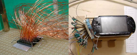
The original PSP may be old news but there is an interesting relic of a website (translated) dedicated to the reverse engineering of a PSP (and exploring Saturn?). To determine the true capabilities of the PSP they desoldered most of the ball grid array chips and then hand soldered 157 jumper wires to allow for direct memory access. In later pictures it shows the PSP hooked up to external hardware for on the fly memory modification. Unfortunately the details are sparse and it doesn’t appear as if they will be updated anytime soon because the website has been “deleted and freezed because of spam. may ineffaceable curse prevail on the spammers.” Still this doesn’t detract too much some very impressive soldering.

DIDJ Composite Video Out

[Nirvous] managed to get composite video out working on the DIDJ. He knew that the CPU had the ability to generate the signal, and that similar devices already had this capability. After studying some DIDJ teardowns he figured out which connection on the processor should provide the appropriate signal. Next was the firmware side of things and after sifting through a lot of code he was pleased to find a flag that looked like it would enable video out. Some cross-compiling, soldering, and a low-pass filter got it to work.

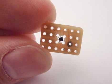
If you’ve been hacking around on the device you might try this. The CPU uses a ball grid array so soldering is a bit difficult. We covered a BGA soldering trick that might be just the thing so check it out before you retreat into your soldering-fortress of solitude.