Cycling Cadence Display With ESP32

Terry Pratchett once said “Wisdom comes from experience. Experience is often a result of lack of wisdom.” This is as true with technical skills as it is with the rest of life, and you won’t truly understand a specific topic unless you’ve struggled with it a bit. [publidave] wanted a simple wireless display for a bluetooth cycling cadence sensor, and soon found himself deep down the rabbit hole of Micropython and Bluetooth Low Energy on the ESP32.

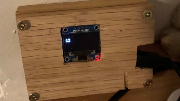
[publidave] had converted his bicycle for indoor training during lockdown and winter, and realized he can’t use the guided training app and view his cadence simultaneously, so he needed a dedicated cadence display. Since [publidave] was comfortable with Python, he decided to give Micropython on the ESP32 ago. Bluetooth Low Energy can be rather confusing if you haven’t implemented it before, especially if good examples are hard to come by. In short, the ESP32 needs to find the sensor, connect to it, select the right service, and listen for the notifications containing the data. The data is then converted to RPM and displayed on a small OLED display. [publidave] does an excellent job of describing what exactly he did, highlighting the problems he encountered, and how he solved them.

In the end, he had a functional display, a good idea of what he would do differently next time, and a lot of additional knowledge and understanding. In our book that’s a successful project.

Since so much of the health related devices work with Bluetooth Low Energy, it could be handy to know the technology and how to interface with it. It would allow you to do things like unbrick a $2000 exercise bike,

TI And Cadence Make PSpice Free

We like simulation software. Texas Instruments long offered TINA, but recently they’ve joined with Cadence to make OrCAD PSpice available for free with some restrictions. You’ve probably heard of PSpice — it’s widely used in academia and industry, but is usually quite costly. You can see a promotional overview video below.

The program requires registration and an approval step to get a license key. The downloaded program has TI models along with other standard models. There seem to be few limits as long as you stick to the supplied library. According to the datasheet, there are no size or simulation complexity limitations in that case. If you want to use other models, you can, but that’s where the limitations hit you:

There is no limitation of how many 3rd party models can be imported into the design. However, if 3rd party models are imported, a user will be able to plot a maximum of 3 signals at a time of their choice when any 3rd party model is imported from web.

We aren’t completely sure what “from web” means there, but presumably they just mean from other sources. In any event, you still get AC, DC, and transient analysis with plenty of options like worst-case timing analysis. Mixed signal designs are supported and there is a wealth of data plotting options, as you would expect.

This is a great opportunity to drive some serious software that is widely used in the industry. The only thing that bummed us out? It runs under Windows. We couldn’t get it to work under Wine, but a Windows 10 VM handled it fine, although we really hate running a VM if we don’t have to.

Still, the price is right and it is a great piece of software. We also liked the recent Micro-Cap 12 release, but we don’t expect any updates for that. Of course, LTSpice is quite capable, too.

Continue reading “TI And Cadence Make PSpice Free”

Cadence Meter Proves Wearable Development Is All About Just Doing It

wearables-just-start-doing


The tech involved in the fitness world really empowers athletes, whether they’re serious or not, to improve their performance by providing empirical evidence. The Striker project focuses on cadence, which is the frequency of strides when running, or revolutions when pedaling. It uses a force sensitive resistor in the shoe to measure footfalls or power strokes.

The concept behind the device is solid, and there are consumer-grade devices already on the market that are capable of performing the same functions. In fact, a Garmin device is used to help measure the accuracy of the system. But we love to see bootstrapped projects, and this one distinguishes itself not only in finished product, but in the process itself. To us it screams: “What are you waiting for, build a prototype and then iterate!”.

The larger image above shows the earliest working version which is just a piece of fabric that wraps around the forearm to hold a 4-digit 7-segment display. The wire following the arm of the wearer snakes all the way down to the shoe to connect with the force sensor. The image to the right is the first wireless version of the readout. But the project has already seen at least two more versions after this one, mostly using SparkFun components.

We think this is but one example of the kind of stuff we want to see as contenders for The Hackaday Prize. The project uses Open Design and it’s arguably a connected device because the sensor and readout connect to each other (but ideally you’d want to add more connectivy to get at the data). The open nature of the build could lead to leaps forward in the technology by affording talented people wider development access.

Continue reading “Cadence Meter Proves Wearable Development Is All About Just Doing It”

Build And Install Your Own High-end Cycling Power Meter

Cycling power meters can set you back quite a pretty penny. [Keith] quotes prices starting at $1500 and going up to $4000. We know several serious cyclists who would think twice about spending that on a bike, and wouldn’t even consider putting that kind of investment into an accessory for it. But if you’ve got the time [Keith] will show you how to build and install your own cycling power meter.

The link above is a roundup of all the posts and videos [Keith] made along the way. We’ve embedded his introduction video after the break where he discusses the goals of the project. The system allows for independently measuring the power of each leg. This is accomplished using strain gauges on the cranks to monitor torque. This data is combined with cadence measurements (how fast the rider is turning the cranks) which is all that is necessary to calculate the power output of the rider.

The parts list comes in at about $350. This doesn’t include the equipment he used to test and calibrate his calculations.

Continue reading “Build And Install Your Own High-end Cycling Power Meter”

Comparing Altium And Cadence PCB Layout Tools

We see a lot of projects using Eagle for the schematics and PCB layout. There are a few that use Kicad, but we hear very little about other alternatives. Recently, [Limpkin] has been working with Altium and Cadence and wrote about how they compare when it comes to PCB layout. Neither are free packages so it’s good to know what you’re getting into before taking the plunge.

[Limpkin] begins his overview by mentioning that the schematic editors are comparable; the differences start to show themselves in the PCB layout tools. Here you can see that Altium always labels the pads so you know what net each of them belongs to. Cadence (whose PCB layout tool is called Allegro) will display the net if you hover over the pad with your mouse. Both have 3D rendering, with Altium’s looking a bit more pleasant but what real use is it anyway? Okay, we will admit we love a good photorealistic board rendering, but we digress. The most interesting differences show themselves once traces are all on the board and need to be rejiggered. Cadence will actually move traces on other layers automatically to avoid collision with a via that is late to the party, and Altium shows some strange behavior when dragging traces. [Limpkin] doesn’t register a final judgement, but the comparison alone is worth the read.

Bike Trainer Computer: Speed, Cadence, Heartrate, Trainer Temp

[Kurt] was using a bike trainer to get in shape for warmer and dryer biking months. Unfortunately it’s pretty hard to train if you don’t have reliable data concerning how hard you’re working. There’s commercial solutions for trainer computers but he’d read some rough reviews about them and decided to build his own trainer computer. He’s done a great job of integrating a lot of different data collection sources. He picked up two replacement bike computer sensors to use on the back wheel for speed (the front wheel is stationary with this type of trainer) and on the crank for cadence. He also wears a heart rate monitor and sourced a SparkFun heart rate module to gather that data. Finally, an LM235 analog temperature sensor was combined with a spring clamp to detect the temperature of the trainer’s resistance module.

Data from the sensors is collected with a PIC16F73 microprocessor and fed to a computer over a serial connection. He’s got a screenshot of the realtime graphs that he’s using for feedback while on the bike. This is a useful and practical setup but when he get’s tired of exercising he’s just a few lines of code from converting this into a gaming controller.

[Thanks Justin]