Rebuilding Dried Out Capacitors

If you’ve ever torn into very old equipment for a little refurbishment, you’ve seen ancient capacitors among tube sockets and carbon resistors. These caps are long past their life expectancy and are dried out. Putting a brand-new metal can cap in a piece of equipment from the 40s just seems wrong, though. Luckily, [unixslave] posted a nice cap rebuilding tutorial on the Hack a Day forum.

To get inside, [unixslave] melted the resin and wax plug at the base of an old cap with a soldering iron. After cleaning out 70-year-old goo with the tip of a flathead screwdriver, he drilled a hole through the core of the cap.

[unixslave] took the old wax-pressed tube of the old cap and put some modern electrolytics inside. The result reminds us of a shady practice happening in a cap factory somewhere, but [unixslave] is keeping everything on the level. The repaired cap has the same value as what’s on the label, just enough to get that old tube amp working.

Do You Know WHY You’re Supposed To Use Decoupling Capacitors?

[Bertho] really enjoyed pawing through the pile of projects submitted to the 7400 logic contest. But one thing kept hitting him with the vast majority of the entries: decoupling capacitors were missing from the circuits. If you’ve worked with microcontrollers or digital logic chips you probably know that you’re supposed to add a small capacitor in between the voltage and ground pins for decoupling purposes. But do you know why? [Bertho] put together a great post that looks that the benefits of using decoupling capacitors in your circuits.

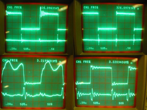
He set up a circuit using a 74HC04 inverter and put it to the test. The image above shows current measurments with the inverter under load. Images on the right show a decoupled circuit and the ones on the left shows a circuit without that capacitor. You can see that the decoupled circuit has much smoother signals when driven high. But it’s not just the smoothness that counts here. [Bertho] goes on to discuss the problem of slow rise-time caused by a dip in current flowing into a chip’s VCC pin. It can take a long time to get above the threshold where a chip would recognize a digital 1. Throwing a capacitor in there adds a little reservoir of current, just waiting to fill in when the power rail dips. This feeds the chip in times of need, keeping those logic transitions nice and snappy.

Roll Your Own Capacitors – High Voltage Edition

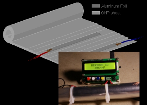
[Grenadier] tipped us off about his method for building your own high-voltage capacitors. He thought the paper and foil capacitor project was a nice introduction to the concepts, but at the same time he knew he could produce a much more powerful device.

For the dielectric he is using acetate film. This is the material from which overhead transparency sheets are made. He stuck with aluminum foil for the two plates. Just roll the foil flat with a rolling-pin, use thin wire to minimize the air that will be trapped between the dielectric layers, and make sure the foil plates are at least 4cm shorter than the acetate film on each end to prevent leakage. After rolling and securing the capacitor with zip ties you’ll be ready for the 3nF worth of fun seen in the video after the break. [Grenadier] mentions that this can be improved further if you were to vacuum impregnate the device with beeswax.

Continue reading “Roll Your Own Capacitors – High Voltage Edition”

Measuring The ~10 Kiloamp Output Of A Large Capacitor Bank

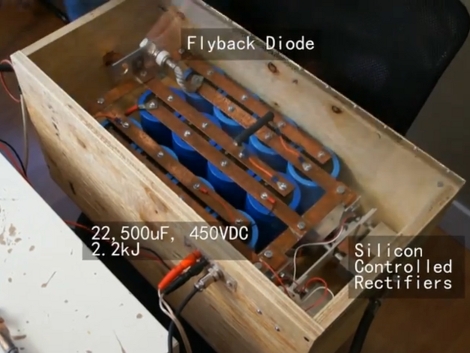
[Norman] put together a rather impressive 22,500 uF capacitor bank. In addition to find things to torture with the strong magnetic field generated by a sudden discharge, he’d like to measure the current pushed from the device. He’s found a way to do this using a digital storage oscilloscope. To protect the oscilloscope [Norman] built his own interface box that includes a 50x voltage divider, and interfaces a current sensor called a Rogowski coil. When it comes time to run the experiment, he turns the safety lock-out key on the bank charger, then discharges the stored potential with the flip of a switch.

Take a look at the video after the break to see soda cans and hard drive platters mangled by the device. The oscilloscope measures the output near 10 kA, giving [Norman] the data he set out to capture. He’s entered this project into the Tektronix contest where it’ll compete with the piano tuner and laser light show tester just to name a few.

Continue reading “Measuring The ~10 Kiloamp Output Of A Large Capacitor Bank”

A-Z Of Electronics – Capacitors

a_to_z_electronics

[Jeri Ellsworth] recently released another video in her “A-Z of Electronics” series – this time Capacitors are the subject. As a penance for my boneheaded AC Capacitor suggestion yesterday (I swear it was lack of sleep talking), [Caleb] suggested that I be the one to write this article. Since I’m not an electrical engineer (I majored in Comp Sci), I enjoy watching these videos, and I share them with individuals who are new to electronics. [Jeri] always presents the subject matter in a clear and concise manner, so the subjects do not seem daunting or intimidating.

She briefly discusses the early development of capacitors, including Leyden Jars, then focuses on modern capacitors and their usage. She covers wiring capacitors in circuits, demonstrating the difference between series and parallel configurations, as well as how electrode distance affects capacitance.

If you have a spare minute, be sure to check out her current video as well as those she has previously released.

Audio Crossover Back In Service


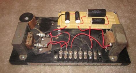
Audio Crossovers are an essential tool for any high end speaker system. Because most individual loudspeakers are unable to cover the entire spectrum of audible sound as well as multiple drivers are, it is necessary to split the input signal into low and high frequency parts. When a friend of [Anthony]’s was about to send off a classic Klipsch AA Crossover to be repaired professionally, [Anthony] insisted it was possible to save some money and do it himself.

The oil can capacitors of the Crossover had gone bad, so a new set of metalized polypropylene capacitors were ordered to pick up the task. After carefully removing the old caps, [Anthony] assembled the new set on a breadboard, and mounted the board to the old Crossover base (along with some tasteful McDonalds straw spacers). The entire process is detailed on his blog, and we are sure his friend saved a good deal by this home repair method. Capacitor issues are a common problem in repairing electronics new and old alike, and always a great place to start looking when devices start acting funny.

Repairing A Broken RC Ceiling Fan

The ceiling fan in [Steve Vigneau’s] bedroom started giving him trouble. It is normally operated using a remote control but that functionality had become pretty spotty. He cleaned the contacts on the remote but still had troubles that could only be fixed by power-cycling the fan itself. When it finally died he set out to repair the unit himself. Above you can see the controller board from the fan. It was a bit too complicated for [Steve] to troubleshoot so he figured why not just stop using the remote control and make it work with a couple of switches? A bit of research led him to some basic fan schematics that he used for a reference. He need to remove a couple of capacitors and wire them up with one switch for the fan and another for the light. Sure, there’s no settings for speed or direction, but [Steve] thinks he doesn’t need to change them and always has the option to add them in the future.