Wall clocks! Are they very accurate? Well, sometimes they are, and sometimes they lose minutes a day. If you’ve got one that needs calibrating, you might like this device from [Lauri Pirttiaho].
Most cheap wall clocks use very similar mechanisms based around the Lavet-type stepper motor. These are usually driven by a chip-on-board oscillator that may or may not be particularly accurate.
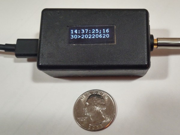
[Lauri] desired a way to tune up these cheap clocks by using GPS-level timing accuracy. Thus began a project based around a CY8KIT evaluation board from Cypress. The microcontroller is paired with a small character LCD as a user interface, and hooked up to a cheap GPS module with an accurate 1-pulse-per-second (1PPS) timing output. The concept is simple enough. Clock drift is measured by using counters in the microcontroller to compare the timing of the GPS 1PPS output and the pulses driving the Lavet-type stepper motor. The difference between the two can be read off the device, and used to determine if the wall clock is fast or slow. Then one need only use a trimmer capacitor to tweak the wall clock’s pulse rate in order to make it more accurate.
Few of us spend much time calibrating low-cost wall clocks to high levels of accuracy. If that sounds like a fun hobby to you, or your name is Garrus, you would probably find [Lauri]’s device remarkably useful. Believe it or not, this isn’t the first clock calibrator we’ve seen, either. Meanwhile, if you’ve brewed up your own high-accuracy timing hardware, feel free to let us know on the tipsline.