The KIM-1 wasn’t the first microcomputer available to computer hobbyists and other electron aficionados, but it was the first one that was cheap. It was also exceedingly simple, with just a 6502 CPU, a little more than 1k of RAM, 2k of ROM, a hexadecimal keypad and a few seven-segment displays. Still, a lot of software was written for this machine, and one of these boards can be found in every computer history museum.
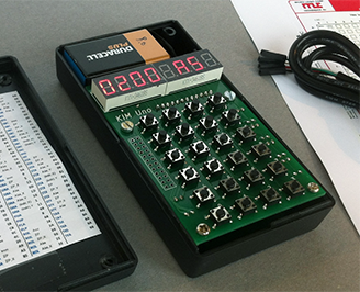
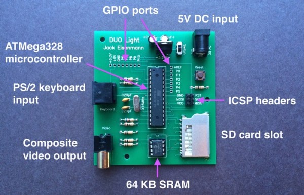
[Oscar] thought the KIM-1 was far too cool to be relegated to the history books so he made his own. It’s not a direct copy – this one uses an Arduino for the brains, only breaking out some buttons, a pair of four-digit seven-segment displays, and the I2C and SPI pins on the ‘duino. The KIM-1 is emulated by the Arduino, allowing for the same interface as an original connected up to an old teletype, and [Oscar] got his hands on the original code for Microchess and the first 6502 disassembler from [Woz] and [Baum].
[Oscar] put the schematics for his version of the KIM-1 up, and has the PCBs up on SeeedStudio. If you’re looking for an awesome replica of a vintage computer and a nice weekend project, here ‘ya go.
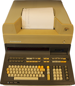 The early days of modern computing were downright weird, and the HP 9830B is a strange one indeed: it’s a gigantic calculator, running BASIC, on a CPU implemented over a dozen cards using discrete logic. In 2014 dollars, this calculator cost somewhere in the neighborhood of $50,000. [Mattis] runs a retrocomputer museum and recently acquired one of these ancient machines,