Over the last few years we’ve seen a few commercial products that aim to put an entire PCB fab line on a desktop. As audacious as that sounds, there were a few booths showing off just that at CES last week, with one getting a $50k check from some blog. [Connor] and [Feiran] decided to do the hacker version of a PCB printer: an old HP plotter converted to modern hardware with a web interface with a conductive ink pen.
The plotter in question is a 1983 HP HIPLOT DMP-29 that was, like all old HP gear, a masterpiece of science and engineering. These electronics were discarded (preserved may be a better word) and replaced with modern hardware. The old servo motors ran at about 1.5A each, and a standard H-Bridge chip and beefy lab power supply these motors were the only part of the original plotter that were reused. For accurate positioning, a few 10-turn pots were duct taped to the motor shafts and fed into the ATMega1284p used for controlling the whole thing.
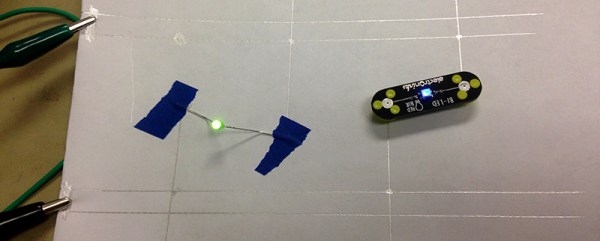
One of the more interesting aspects of the build is the web interface. This is a small JavaScript app that is capable of drawing lines on the X and Y axes and sends the resulting coordinates from a server to the printer. It’s very cool, but not as cool as the [Connor] and [Feiran]’s end goal: using existing Gerber files to draw some traces. They’re successfully parsing Gerber files, throwing out all the superfluous commands (drills, etc), and plotting them in conductive ink.
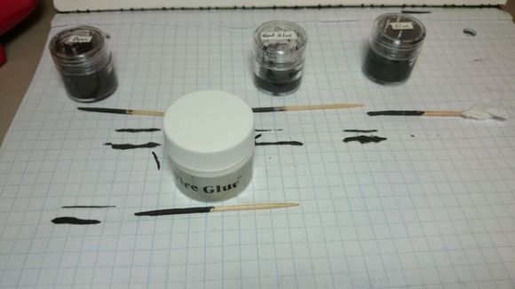
The final iteration of hardware wasn’t exactly what [Connor] and [Feiran] had in mind, but that’s mostly an issue with the terrible conductivity of the conductive ink. They’ve tried to fix this by running the pen over each line five times, but that introduces some backlash. This is the final project for an electrical engineering class, so we’re going to say that’s alright.
Video below.
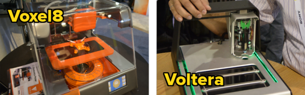
![[Michael Bell] poses with the Voxel8](https://i0.wp.com/hackaday.com/wp-content/uploads/2015/01/dsc_0405.jpg?w=530&h=353&ssl=1 "DSC_0405")


![[Alroy Almeida] poses with the Voltera](https://i0.wp.com/hackaday.com/wp-content/uploads/2015/01/dsc_0432.jpg?w=524&h=350&ssl=1 "DSC_0432")