Looking For Pi In The 8087 Math Coprocessor Chip

Even with ten fingers to work with, math can be hard. Microprocessors, with the silicon equivalent of just two fingers, can have an even harder time with calculations, often taking multiple machine cycles to figure out something as simple as pi. And so 40 years ago, Intel decided to give its fledgling microprocessors a break by introducing the 8087 floating-point coprocessor.

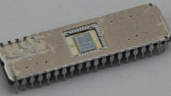
If you’ve ever wondered what was going on inside the 8087, wonder no more. [Ken Shirriff] has decapped an 8087 to reveal its inner structure, which turns out to be closely related to its function. After a quick tour of the general layout of the die, including locating the microcode engine and ROM, and a quick review of the NMOS architecture of the four-decade-old technology, [Ken] dug into the meat of the coprocessor and the reason it could speed up certain floating-point calculations by up to 100-fold. A generous portion of the complex die is devoted to a ROM that does nothing but store constants needed for its calculation algorithms. By carefully examining the pattern of NMOS transistors in the ROM area and making some educated guesses, he was able to see the binary representation of constants such as pi and the square root of two. There’s also an extensive series of arctangent and log2 constants, used for the CORDIC algorithm, which reduces otherwise complex transcendental calculations to a few quick and easy bitwise shifts and adds.

[Ken] has popped the hood on a lot of chips before, finding butterflies in an op-amp and reverse-engineering a Sinclair scientific calculator. But there’s something about seeing constants hard-coded in silicon that really fascinates us.

CORDIC Brings Math To FPGA Designs

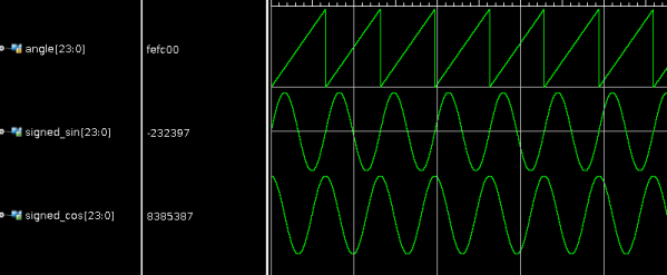
We are always excited when we see [Hamster] post an FPGA project, because it is usually something good. His latest post doesn’t disappoint and shows how he uses the CORDIC algorithm to generate very precise sine and cosine waves in VHDL. CORDIC (Coordinate Rotation Digital Computer; sometimes known as Volder’s algorithm) is a standard way to compute hyperbolic and trigonometric functions. What’s nice is that the algorithm only requires addition, subtraction, bit shifts, and a lookup table with an entry for each bit of precision you want. Of course, if you have addition and negative numbers, you already have subtraction. This is perfect for simple CPUs and FPGAs.

[Hamster] not only has the VHDL code but also provides a C version if you find that easier to read. In either case, the angle is scaled so that 360 degrees is a full 24-bit word to allow the most precision. Although it is common to compute the result in a loop, with the FPGA, you can do all the math in parallel and generate a new sample on each clock cycle.

Continue reading “CORDIC Brings Math To FPGA Designs”

Signal Generator Uses FPGA

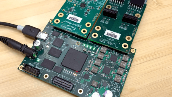
Although there are a few exceptions, FPGAs are predominantly digital devices. However, many FPGA applications process analog data, so you often see an FPGA surrounded by analog and digital converters. This is so common that Opal Kelly — a producer of FPGA tools — launched the SYZYGY open standard for interconnecting devices like that. [Armeen] — a summer intern at Opal Kelly — did a very interesting open source FPGA-based signal generator using a Xilinx FPGA, and a SYZYGY-compliant digital to analog converter.

As you might expect, [Armeen] used a lot of Opal Kelly hardware and software in the project. But the Verilog code (available on GitHub) shows a lot of interesting things including some very practical example code for using Xilinx CORDIC IP,  which is a great way to do high-order math using digital logic.

Continue reading “Signal Generator Uses FPGA”