$2 FM Transmitter For Raspberry Pi

We love re-purposed consumer gear. This project uses a cheap, discontinued cellphone gadget to create a Raspberry Pi controlled FM radio transmitter.

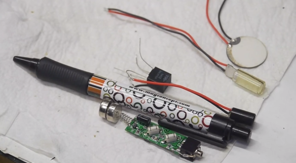
The Sony-Ericsson MMR-70 radio transmitter apparently used to connect to a cell phone and broadcast music. But the Walkman cellphones in question are a little bit old in the tooth, so one can buy the transmitter units for cheap on the resale market. What makes the transmitters even more interesting is that you can activate and deactivate the radio, change frequency or output power, and even send RDS station and song information.

It turns out (link in German) that the radios have an AVR ATMega32 microcontroller and a NS73 radio transmitter module, which can be entirely controlled over I2C. (Schematic here as PDF.) The units also have handy test points strewn all around. Once the test points were mapped out, one could completely ignore the on-board AVR microcontroller and control the FM transmitter module directly using the Raspberry Pi’s I2C outputs.

And that’s where [Manawyrm] stepped in. She wrote an I2C daemon for the Raspberry Pi that lets you control the FM transmitter via simple commands. All you have to do is solder up a bunch of test points, install [Manawyrm]’s software, write a batch script, and you’re on the air. For instance, this makes building a FM radio retransmitter for online streamed audio a one-day project. You can see his working example on youtube. Of course, you’ll want a web-based remote control interface to go with that.

If you’re interested in hacking along, and don’t have a Raspberry Pi application in mind, Sparkfun used to sell the NS73 radio transmitter so you can find lots of good information about the chip. We’d love to see a stand-alone broadcasting gizmo that actually utilizes the onboard AVR chip, but our hats are off to [Manawyrm] for making the Raspberry Pi version so accessible.

Dusty Junk-bin Downconverter Receives FM On An AM Radio

This amateur radio hack is not for the faint of heart! With only three transistors (and a drawer-full of passive parts), [Peter Parker, vk3ye] is able to use a broken-looking AM car radio to receive FM radio signals (YouTube link) on 2 meters, an entirely different band.

There are two things going on here. First, a home-made frequency downconverter shifts the 147 MHz signal down to the 1 MHz neighborhood where the AM radio can deal with it. Then, the AM radio is tuned just slightly off the right frequency and the FM signal is slope detected.

The downconverter consists of a local tuned oscillator and a mixer. The local oscillator generates an approximate 146 MHz signal from an 18 MHz crystal, accounting for two of the three transistors. Then this 146 MHz signal and the approximately 147 MHz signal that he wants to listen to are multiplied together (mixed) using the third transistor.

If you’re not up on your radio theory, a frequency mixer takes in two signals at different frequencies and produces an output signal that has various sums and differences of the two input signals in it. It’s this 147 MHz – 146 MHz = 1 MHz FM signal, right in the middle of the AM radio band’s frequency range, that’s passed on to the AM radio.

Next, the AM radio slope detects the frequency-modulated (FM) signal as if it were amplitude modulated (AM). This works as follows: FM radio encodes audio as changes in frequency, while AM radios encode the audio signal in the amplitude, or volume, of the radio signal. Instead of tracking the changing frequency as an FM radio would, slope detectors stick on a single frequency that’s tuned just slightly off from the FM carrier frequency. As the FM signal gets closer to or farther away from this fixed frequency, the received signal gets louder or quieter, and FM is detected as AM.

At 5:23, [vk3ye] steps through the circuit diagram. As he mentions, these are old tricks from circa 50 years ago, but it’s very nice to see a junk-box hack working so well with so few parts and receiving (very) high frequency FM on an old AM car radio. A circuit like this could make a versatile front end for an SDR setup. It makes us want to warm up the soldering iron.

Continue reading “Dusty Junk-bin Downconverter Receives FM On An AM Radio”

THP Semifinalist: A Continuous Wave Radar

There aren’t many Hackaday Prize entries playing around in RF, save for the handful of projects using off the shelf radio modules. That’s a little surprising to us, considering radio is one of the domains where garage-based tinkerers have always been very active. [Luke] is bucking the trend with a FM continuous wave radar, to be used in experiments with autonomous aircraft, altitude finding, and synthetic aperture radar imaging.

[Luke]’s radar operates around 5.8-6 GHz, and is supposed to be an introduction to microwave electronics. It’s an extremely modular system built around a few VCOs, mixers, and amplifiers from Hittite, all connected with coax.

So far, [Luke] has all his modules put together, a great pair of cans for the antennas, everything confirmed as working on his scope, and a lot of commits to his git repo.

You can check out [Luke]’s demo video is available below.


SpaceWrencherThe project featured in this post is a quarterfinalist in The Hackaday Prize.

Continue reading “THP Semifinalist: A Continuous Wave Radar”

A Dead Simple, Well Constructed FM Transmitter

[Angelo] is only 15, but that doesn’t mean his fabrication skills are limited to Lego and K’Nex. He’s built himself an amazingly well constructed FM transmitter that’s powerful enough to be received a quarter mile away.

The FM transmitter circuit itself is based off one of [Art Swan]’s builds, but instead of the solderless breadboard construction you would expect to find in a small demo circuit, [Angelo] went all the way, etching his own PCB and winding his own coil.

Using photosensitized copper clad board, [Angelo] laid out the circuit with Fritzing, etched a board, and went at it with a drill. The components found in the transmitter are pretty standard and with the exception of the trimmer cap and electret mic, can be picked up in the parts drawers of any Radio Shack. He gets bonus points for using a 1/4 – 20 bolt for winding the coil, too.

The power supply for the transmitter is a single 9V battery, the battery connector being salvaged from a dead 9V. Awesome work, and for someone so young, [Angelo] already seems to have a grasp of all the random, seemingly useless information that makes prototyping so much easier. Video below.

Continue reading “A Dead Simple, Well Constructed FM Transmitter”

The Basics Of Frequency Modulation

fm-modulation

[brmarcum] takes us back to analog building block basics with his Frequency Modulation and Demodulation tutorial. Frequency Modulation (FM) sounds simple at first, but understanding the electronics behind modulation and  demodulation of an FM signal can be confusing. We’ve covered the basics before, but FM is so tightly associated with broadcast radio that searches often become muddled with references to RF, stereo, antennas, and transmitters.

[brmarcum] hopes to fill that gap with a simple circuit that modulates an audio signal to FM, then demodulates and amplifies it to be played on a small speaker. He used a Digilent Analog Discovery kit in his experiments, but an oscilloscope (an older analog scope would be perfect here) would work for output. Signal generation duties could easily be handled by a 555 circuit at the low end, and a computer sound card at the higher end.

[brmarcum] obviously put some time into his tutorial, but it’s not a tome of FM modulation. He’s broken down the modulation and demodulation circuits into their basic op-amp stages with examples of what the signal should look like on a scope after each stage. That’s the beauty here. By building and testing each section, anyone new to analog can learn how things work. In places where the theory behind what’s going on gets too in-depth for an Instructable, [brmarcum] gives links to Wikipedia.

RasPi FM Transmitter

Easily Turn Your Raspberry Pi Into An FM Transmitter

Have you ever wanted to be your own radio DJ? [Kevin] has made it easier than ever with his Raspberry Pi FM Transmitter program. The program is written in C. [Kevin] has made source code is available along with a compiled binary.

PIFM allows you to load up any audio file and specify a frequency to transmit. The program will then use PWM to modulate the audio sample through the Pi’s GPIO4 pin. [Kevin] claims that the RasPi alone will only transmit around a 10 cm distance. He says that making a simple antenna out of a jumper wire can increase the distance to around 100 meters. All you have to do is hook up the wire to the GPIO4 pin to drastically increase the range.

The legality of such a transmitter will vary from place to place, so be sure to check out your local regulations before you go transmitting audio on regulated frequencies. If this kind of thing is interesting to you, you may want to investigate ham radio. It’s not all Morse code and old fogies. Some people claim it’s a hacker’s paradise.

[via Reddit]

Controlling RC Toys With The Raspi

signal

An interesting trick you can do with a a fast CPU and a GPIO pin mapped directly to memory is an FM transmitter. Just toggle a pin on and off fast enough, and you have a crude and kludgy transmitter. [Brandon] saw a few builds that turned a Raspberry Pi into an FM radio transmitter and realized a lot of toy remote control cars use a frequency in the same range a Pi can transmit at. It’s not much of a leap to realize the Pi can control these remote control cars using only a length of wire attached to a GPIO pin.

The original hack that turned a Pi GPIO pin into an FM transmitter mapped a GPIO pin to memory, cycled through that memory at about 100 MHz, and added a fractional divider to slightly adjust the frequency, turning it into an FM transmitter. Cheap RC cars usually listen for radio signals at 27 and 49 MHz. It doesn’t take much to realize commanding RC cars with a Pi is possible.

The only problem with this idea is that most RC cars use pulse modulation. For an RC transmitter to send the command for ‘forward’, a synchronization pulse is sent, then a series of pulses and pauses. The frequency doesn’t change at all, something the originally FM code doesn’t do. [Brandon] realized that if he just moved the frequency up to something the RC car wasn’t listening to, that would register as a zero.

All that was left was to figure out the command codes for his RC truck. For this, [Brandon] decided brute force would be the best option. Armed with a script and a webcam, he cycled through all possible combinations until the webcam detected a moving truck. Subtlety brilliant, if you ask us. Of course more complex commands required an oscilloscope, but now [Brandon] has a git full of all the code to control a cheap RC car with a Pi.