Sucking PIC Firmware Out Of An Old APC Battery Backup

reverse-engineering-pic-firmware-of-APC-power-supply

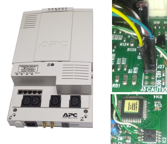
Looking at this huge Uninterruptible Power Supply we are a little envious. It’s meant to hang on the wall of a utility room and power your critical devices. [Radek Hvizdos] has had it in service for quite some time, and when he started thinking of replacing the internal battery he decided to see if he could also extend the functionality. To do so he needed to get at the firmware of the chip controlling the device. And so began his adventure of dumping the firmware from the read-protected PIC 18F452.

The challenge of dumping code from a write-protected chip is in itself a fun project. But [Radek] was actually interested in fixing bugs and adding features. The wishlist feature we’d be most interested in is a kind of triage for shutting down devices as the internal battery starts to run low. Nice! But starting from scratch with the firmware is a no-go. You can see the two places where he connected to the PCB. The upper is for using a PIC programmer. The lower is an I2C connection used to dump the EEPROM with an improvised Bus Pirate.

In the end it was improper lock bit settings that opened the door to grabbing the firmware. The bootloader section of the PIC is not locked, and neither is the ability to read from FLASH at run-time. These two combined allowed him to write his own code which, when flashed to the bootloader section, dumps the rest of the firmware so that it may be combined into a complete file afterward. Since posting this fascinating article he has made a follow-up about disassembling the code.

3d Printed Hexapod Robot

3d-printed-hexapod

This hexapod was made almost entirely via 3d printing (translated). The parts that you need to supply include a few fasteners to make connections, twelve servo motors, and a method of driving them. As you can see in the video after the break, all those parts come together into a little robot that functions quite well. The only thing that we think is missing are some grippy feet to help prevent slipping.

[Hugo] calls the project Bleuette. It is completely open source, with the cad files and source code available on his Github repository. There is additional information in the wiki page of that repo. This gives us a good look at the electronic design. He’s controlling the legs with an Arduino, but it’s all dependent on his own shield which features a PIC 18F452 to take care of the signals used to drive all of the servo motors. The board also has some peripherals to monitor the current draw and regulate the incoming power.

Continue reading “3d Printed Hexapod Robot”

38 KHz IR Communications Tutorial

Learning about how infrared remote controls work is a great way to expand your electronics knowledge. That’s because this technology is invisible to our eye, and happening faster than we can comprehend without help from test equipment. This tutorial over at Pyroelectro talks about the theory behind how the data is transferred and shows you how to build a couple of circuits to experiment with and communicate through infrared light transmissions.

Instead of going with an IR receiver module you’ll build your own using a photo-transistor and an operational amplifier. The Opamp is used to amplify and invert the signal picked up from the IR transmission of a common home entertainment remote control. From there the digital signal is read by a PIC 18F452 microcontroller for processing. But if you want to use a different microcontroller there’s still more than enough usable information to get you across the finish line.

Simple Sensors To Calculate RPM

Ever wonder how to calculate revolutions per minute using a microcontroller? This project shows you how by purposing an IR emitter and detector and a computer fan. As the fan blades spin they disrupt the beam of infrared light between the emitter and the receiver. This results in a waveform on the receiver’s circuit which can be easily used to trigger interrupts in any microcontroller. In this case a PIC 18F452 monitors the detector’s signals for a rising edge. By measuring time data between interrupts the period can be established and RPM calculated. You can see a video of the test rig after the break.

So what can you use this for? It’s the method that most spinning POV displays use to stabilize the display. You won’t be limited to an IR sensor, but can use a hall effect sensor in the same basic fashion.

Continue reading “Simple Sensors To Calculate RPM”

Control A TV With GLCD Commands

[youtube=http://www.youtube.com/watch?v=t3gMjuVdQnA]

This hack lets you use a TV in place of a graphic LCD screen. But we like to think of this less as a replacement for a GLCD and more of a simple way to get your information onto a television. A PIC 18F452 acts as a translator between the GLCD parallel inputs and a composite video output. There are some malformed image links on the page which we’ve fixed and linked to after to the break so that you can take a look at the schematic, component layout, and PCB artwork. The assembler code and hex file are available for download but you’ll need to register to get access to them.

Working image links:

[Thanks Flacoclau]