Using A Lecher Line To Measure High Frequency

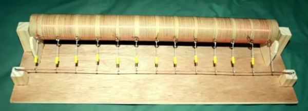
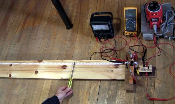
How do you test the oscillator circuit you just made that runs between 200MHz and 380MHz if all you have is a 100MHz oscilloscope, a few multimeters and a DC power supply? One answer is to put away the oscilloscope and use the rest along with a length of wire instead. Form the wire into a Lecher line.

That’s just what I did when I wanted to test my oscillator circuit based around the Mini-Circuits POS-400+ voltage controlled oscillator chip (PDF). I wasn’t going for precision, just verification that the chip works and that my circuit can adjust the frequency. And as you’ll see below, I got a fairly linear graph relating the control voltages to different frequencies.

What follows is a bit about Lecher lines, how I did it, and the results.

Continue reading “Using A Lecher Line To Measure High Frequency”

Two Guys, A Hotel Room And A Radio Fire

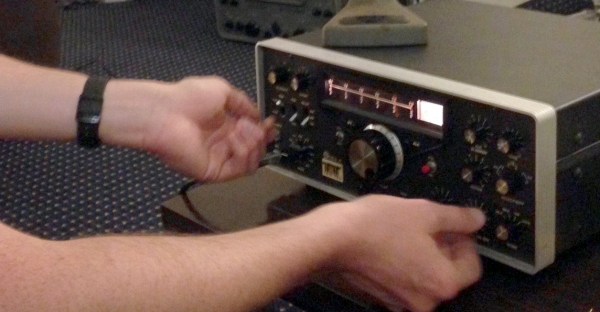
Can you build a HF SSB radio transciever in one weekend, while on the road, at parts from a swap meet? I can, but apparently not without setting something on fire.

Of course the swap meet I’m referring to is Hamvention, and Hamvention 2016 is coming up fast. In a previous trip to Hamvention, Scott Pastor (KC8KBK) and I challenged ourselves to restore tube radio gear in a dodgy Dayton-area hotel room where we repaired a WW2 era BC-224 and a Halicrafters receiver, scrounging parts from the Hamfest.

Our 2014 adventures were so much fun that it drove us to create our own hacking challenge in 2015 to cobble together a <$100 HF SSB transceiver (made in the USA for extra budget pressure), an ad-hoc antenna system, put this on the air, and make an out-of-state contact before the end of Hamvention using only parts and gear found at Hamvention. There’s no time to study manuals, antennas, EM theory, or vacuum tube circuitry.  All you have are your whits, some basic tools, and all the Waffle House you can eat.  But you have one thing on your side, the world’s largest collection of surplus electronics and radio junk in one place at one time.  Can it be done?

Continue reading “Two Guys, A Hotel Room And A Radio Fire”

Hacklet 80 – Gigahertz Projects

Somewhere between the HF projects many of us have worked on, and the visible light spectrum lies the UHF, EHF, SHF, and THF. That’s Ultra, Extremely, Super, and Tremendously High Frequency for those who aren’t in the know. All of them involve frequencies in the gigahertz and terahertz range. While modern computers have made gigahertz a household term, actually working with signals in the gigahertz frequency range is still a daunting prospect. There have always been an elite group of hackers, makers, and engineers who tinker with projects using GHz frequencies. This week’s Hacklet is about some of the best GHz projects on Hackaday.io!

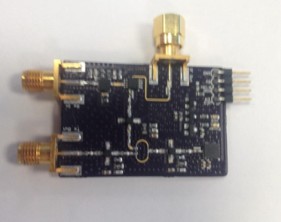
radar1We start with [Luke Weston] and Simple, low-cost FMCW radar. For years people like Hackaday’s own [Gregory L. Charvat] have been building simplified radar systems and documenting them for the rest of us. [Luke’s] goal is to make radar systems like this even more accessible for the average hacker. He’s put all the specialized parts on one board. Rather than large Mini Circuits modules, [Luke] went with Hittite microwave parts in chip scale packages. Modulation comes from a Microchip MCP4921 mixed signal DAC. The system works, and has demonstrated transmission and reception 5 GHz to 6 GHz bands. [Luke] has even demonstrated detection of objects at close range using a scope.

Continue reading “Hacklet 80 – Gigahertz Projects”

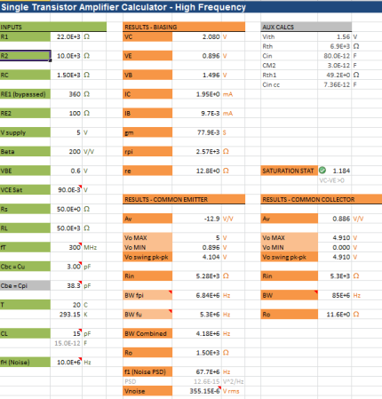
An Excel Based High Frequency Transistor Amplifier Calculator

amplifier calculator


[Paulo] just tipped us about an Excel based high frequency transistor amplifier calculator he made. We’re guessing that some of our readers already are familiar with these class A amplifiers, commonly used to amplify small audio signals. Skipping over the fact that their efficiency is quite low — they are cheap to make, don’t require many components and usually are a great way to introduce transistors to new electronics enthusiasts. All you usually need to do is a few calculations to properly set your output signals and you’re good to go.

Things are however more complex when you are amplifying 200MHz+ signals, as all the components (complex) impedances have to be taken into account so you can get a nice amplification system. On a side note, at these frequencies your transmission lines impedances may even vary depending on how much solder and flux you left on your SMT pads along the way. [Paulo]’s calculator will therefore compute most of the characteristics of two class A common emitter/collector amplifiers for specified loads.


Induction Furnace

induction furnace

[Tim Williams] made his own induction furnace. A copper tubing coil forms the primary winding, as the material to be heated becomes the short circuited secondary. The load material is subject to high power magnetic fields operating at radio frequency. The rapidly changing field induces current flow within the material, creating a great deal of heat. The brute power required a cooling system to match. In the video below, the induction furnace can be seen melting common table salt.

Continue reading “Induction Furnace”