ATtiny85 Sketch Flashing Rig

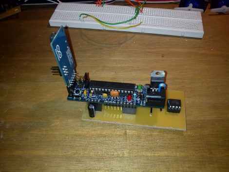
We’re happy to see Arduino enthusiasts championing the use of smaller hardware when the need for a full-blown ATmega-based board just isn’t there. [Chris] has been doing just that, using ATtiny85 chips in his projects. But he’s tired of hooking jumper wires to flash the sketches. He finally got around to etching this ATtiny85 programming adapter.

If the project is not pin hungry, an ATtiny85 can run Arduino sketches without the need to port the code. The best news is that the Arduino board you used to prototype the project can be used as the programmer for the standalone chip. Here that’s a Boarduino, and [Chris] laid out a double row of female pin headers for quick plug-in. To the right you can see the DIP socket for the target chip. Although this works perfectly well, we would have liked to also see the inclusion of a 2×3 AVR ISP programming header which could be used with the full range of AT chips.

Building An EEPROM Programmer

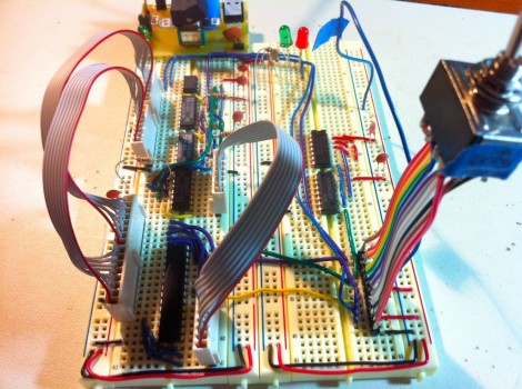
Behold this ATtiny85 based EEPROM programmer. It seems like a roundabout way of doing things, but [Quinn Dunki] wanted to build to her specifications using tools she had on hand. What she came up with is an ATtinyISP USB programmer, pushing data to an ATtiny85, which then programs an EEPROM chip with said data.

The hardware is the next module for her Veronica 6502 computer build. When we last saw that project [Quinn] was planning to add persistent storage for the operating firmware. This will be in the form of an EEPROM programmed with this device. Using ISP and an ATtiny as a go-between means that she should have no problems reflashing the OS without removing the chip. But it all depends on how she designs the interface.

For example, she blew a whole bunch of time troubleshooting the device because garbage data was being written to the chip. In the end, having her manual bus programmer hooked up during the flashing operation was the culprit. Lesson learned, it’s onward and upward with the build.

We’ve been featuring [Quinn’s] projects a lot lately. That’s in part because they’re really interesting, but also because she does such a great job of documenting her experience.

Build A Binary Wall Clock For Just A Few Bucks

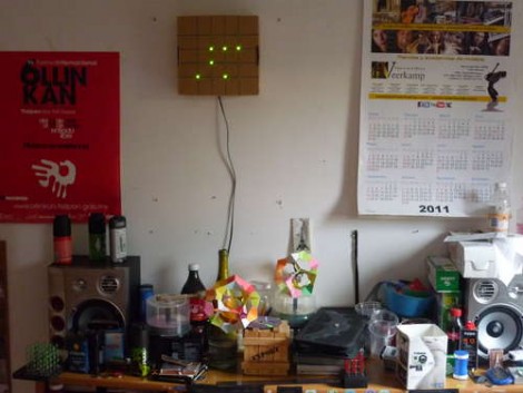
The weekend is almost here and if you’re looking for an afternoon project consider building your own binary wall clock. [Emihackr97] built the one you see above using parts on hand, but even if you put in an order for everything, it won’t cost you much.

He used a cardboard box as the housing for the clock, marking a grid for the LEDs on the face and drilling holes to house them. Two columns for hours and another two for minutes let the clock display 24-hour time with alternate firmware for 12 hour time. Since there are two buttons – one to set hours, the other to set minutes – a little coding would make it possible to select between the two either by clicking both buttons at once, or holding down one button.

[Emihackr97] is driving the display with an ATmega48, which is a pin-compatible replacement for the ATmega168/328. Those chips are the type most commonly found on Arduino boards an indeed this project is running the Arduino bootloader, but uses an ISP programmer and breadboarded circuit to keep the costs low. There are plenty of pins to drive the 13 LEDs directly, making the soldering quick and painless. Check out a demo clip after the break.

If you’re successful at this build and get the itch for something with more style, there’s a ton of ways to spice up the look of a binary clock.

Continue reading “Build A Binary Wall Clock For Just A Few Bucks”

Bootloader Burning Basics

[Charles Gantt] and a few others were having trouble burning the Sanguino bootloader to an ATmega644 chip. With some help from the [Nils Vogil] via the RepRap IRC [Charles] got it worked out and wrote a guide for burning the bootloader using an Arduino as an ISP programmer.

We’re not familiar with the specifics of the Sanguino bootloader, but [Charles] mentioned that he was unable to flash it onto the AVR chip without a resonator. The resonator serves as an external clock source for the chip. We’d bet the programming process changes the fuse settings on the chip to use an external source. Without that source, you won’t be able to communicate with the chip afterwards.

The solution just adds the resonator to the programming circuit. This should be useful when burning any bootloader using an Arduino. But it does make us wonder if there isn’t an alternative method that would let you draw the clock signal from the Arduino itself?

AVR Programmer Modelled After The MkII – Uses LUFA

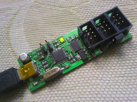
Here’s a new option for building your own AVR programmer. It’s called the MkII Slim and the diminutive size makes it live up to its name. The design is rather spartan, using just three chips; a voltage regulator, a MAX3002 level converter, and an Atmel AT90USB162 as the main microcontroller. This chip has a built-in USB module, foregoing the need for a separate FTDI chip.

The firmware is built on the Lightweight USB Framework for AVRs (LUFA). This is a USB stack implementation originally called MyUSB that was developed by [Dean Camera]. Regular lurkers over at the AVRfreaks forums will recognize [Dean’s] name, or his handle [abcminiuser] as a source for many of the high quality AVR tutorials found there. But we digress.

The programmer offers all the features you’d want in an In-System Programmer. It can easily be reflashed with future updates thanks to the bootloader running on the chip. There’s jumper-selectable power options, and it can program targets running at 3.3V or 5v. The full development package including code and artwork is available for download at the site linked above. For your convenience we’ve embedded the schematic after the break.

Continue reading “AVR Programmer Modelled After The MkII – Uses LUFA”

Programming An ATtiny Using An Arduino

attiny

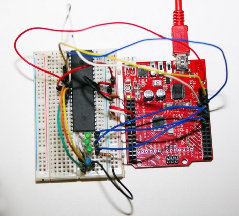
[Scott] is a big fan of the Arduino platform, and he’s not afraid to admit it. It does all the things he needs, but now and again he would like to use something a bit smaller, without all the bells and whistles the Arduino has to offer. He contemplated using an ATtiny for smaller projects, but after looking into what he would need to program the chip under Linux, he could never find the motivation to give it a go.

That all changed when he discovered the Arduino-Tiny project, which aims to bring a limited Arduino IDE to the ATtiny line of microcontrollers. He found the project to be quite useful, so he put together a brief tutorial that walks through everything you need to get started.

The tutorial is fairly straightforward, and even demonstrates how the Arduino can be used as an ISP for the ATtiny, removing the need to purchase a standalone programmer. Be sure to check it out if you are searching for an easy way to get started with ATtiny chips under Linux.

AVR HVSP On A Tiny Breadboard

AVR chips are convenient because you can program them in circuit at their operating voltage. That is, unless you screw up the fuse settings and they’ll no longer listen to an In System Programmer. If you find yourself facing this problem, just build this circuit on a breadboard and ‘unbrick’ by holding down the button.

The circuit seen above is a High Voltage Serial Programmer. This is one of two high voltage protocols used by AVR chips; HVSP is for chips that don’t have enough pins to use High Voltage Parallel Programming. This rendition uses a 12V power source, which is the level necessary for the high voltage method. A 7805 linear regulator joins the mix to provide operational voltage, along with one transistor, an ATtiny2313 to control the circuit, a four-digit 7-segment display for feedback, and one button for control.

Watch the video after the break to see an ATtiny13 programmed to disable the reset pin using a breadboarded programmer. That chip is then easily rescued, having been automatically recognized by using its device signature.

Continue reading “AVR HVSP On A Tiny Breadboard”