We’ve always been fascinated by things that perform complex electronic functions merely by virtue of their shapes. Waveguides come to mind, but so do active elements like filters made from nothing but PCB traces, which is the subject of this interesting video by [FesZ].
Of course, it’s not quite that simple. A PCB is more than just copper, of course, and the properties of the substrate have to be taken into account when designing these elements. To demonstrate this, [FesZ] used an online tool to design a bandpass filter for ADS-B signals. He designed two filters, one using standard FR4 substrate and the other using the more exotic PTFE.
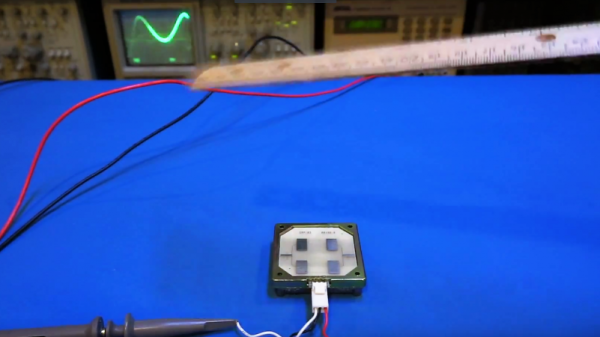
He put both filters to the test, first on the spectrum analyzer. The center frequencies were a bit off, but he took care of that by shortening the traces slightly with a knife. The thing that really stood out to us was the difference in insertion loss between the two substrates, with the PTFE being much less lossy. The PTFE filter was also much more selective, with a tighter pass band than the FR4. PTFE was also much more thermostable than FR4, which had a larger shift in center frequency and increased loss after heating than the PTFE. [FesZ] also did a more real-world test and found that both filters did a good job damping down RF signals across the spectrum, even the tricky and pervasive FM broadcast signals that bedevil ADS-B experimenters.
Although we would have liked a better explanation of design details such as via stitching and trace finish selection, we always enjoy these lessons by [FesZ]. He has a knack for explaining abstract concepts through concrete examples; anyone who can make coax stubs and cavity filters understandable has our seal of approval.
Continue reading “Making PCB Strip Filter Design Easy To Understand”