Solderless Noise-o-Tron Kit Makes Noise At Chicago Makerfaire

Noise-o-Tron

Anyone who’s manned a hackerspace booth at an event knows how difficult it can be to describe to people what a hackerspace is. No matter what words you use to describe it, nothing really seems to do it justice. You simply can’t use words to make someone feel that sense of accomplishment and fun that you get when you learn something new and build something that actually works.

[Derek] had this same problem and decided to do something about it. He realized that in order to really share the experience of a hackerspace, he would have to bring a piece of the hackerspace to the people.  That meant getting people to build something simple, but fun. [Derek’s] design had to be easy enough for anyone to put together, and inexpensive enough that it can be produced in moderate quantities without breaking the bank.

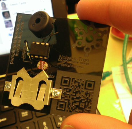
[Derek] ended up building a simple “optical theremin”. The heart of this simple circuit is an ATTiny45. Arduino libraries have already been ported to this chip, so all [Derek] had to do was write a few simple lines of code and he was up and running. The chip is connected to a photocell so the pitch will vary with the amount of light that reaches the cell. The user can then change the pitch by moving their hand closer or further away, achieving a similar effect to a theremin.

[Derek] designed a simple “pcb” out of acrylic, with laser cut holes for all of the components. If you don’t have access to a laser cutter to cut the acrylic sheets, you could always build your own. The electronic components are placed into the holes and the leads are simply twisted together. This allows even an inexperienced builder to complete the project in just five to ten minutes with no complicated tools. The end result of his hard work was a crowded booth at a lot of happy new makers. All of [Derek’s] plans are available on github, and he hopes his project will find use at Makerfaires and hackerspace events all over the world.

Cordwood Puzzle Kit Without Instructions

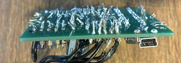
What you see above is a cordwood circuit, an interesting circuit construction technique from before the days of integrated circuits. The circuit consists of two circuit boards arranged parallel to each other with components holding them apart. This was, for its day, the densest circuit construction technique, used in everything from late 50s aerospace tech to huge computers that filled rooms.

The folks over at Boldport have a love for interesting PCBs and are apparently aficionados of antiquated tech, leading them to create their own cordwood circuit. Here’s the best part: it’s a kit, without assembly instructions.

The cordwood puzzle assembles into a bunch of LEDs that will light up when power is applied. Not much, but there’s a few FETs in there that allow you to control them all individually with a microcontroller. The real fun is trying to assemble the kit: both sides of the cordwood circuit are identical, meaning there’s going to be holes that aren’t meant to be filled, components that will need to be soldered, and most likely a bit of swearing.

Still, this is an exceptionally small circuit for something using this construction technique. If you know of a denser and more modern cordwood circuit out there, leave a note in the comments. If you want to know what the kit looks like when it’s built, [Phil Wright] has your back.

Impersonating FBI Agents And People Who Can Solder

[Dale Botkin], [N0XAS], is a competent designer for the amateur radio crowd and has a part-time business on the side selling a few kits. As anyone who owns a business, works in retail, or simply interacts with the general population will know, eventually you’ll have to deal with one of those customers. [Dale]’s latest horror story (here’s the coral cache but that doesn’t seem to be working either) comes from someone who bought a little repeater controller. You’re looking at this customer’s handiwork above. It gets worse.

After this customer completely botched an assembly job, he contacted [Dale] for some technical assistance. [Dale] graciously accepted a return and received the above mess of solder, wires, and parts. Then an email disputing the Paypal charge arrived. The customer wanted a refund for the original kit and the cost of shipping it back.

Oh, but it gets better. After posting this story, [Dale] received yet another email from an FBI agent demanding that his original post be taken down. The email from the FBI came from a Czech domain, so of course this is a totally legit demand.

So there’s your, “worst customer ever” story from the world of kit electronics. The assembly is impressively bad, even for something that was ‘professionally installed by an electrician’, but mail fraud and impersonating federal officials just takes this over the top.


Quick note: any doxxing in the comments will be deleted, so just don’t do it.

Artemis Synthesizer Kit

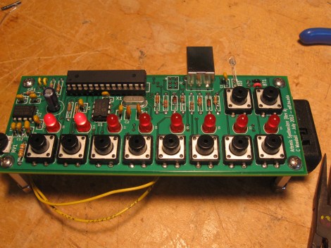
The Artemis Synthesizer was created as a kit for Boston University’s Artemis Project. This project aims to teach female rising high school freshmen about computer science with hands-on activities. [Chris] based the kit on a ATMEGA328P microcontroller and a MCP4921 digital to analog converter. It can be used in a keyboard mode, where the buttons toggle various notes of the scale, or in a sequencer mode, where the buttons are used to toggle pre-programmed sequences.

[Chris] wanted the kit to be usable by the students after the workshop, so he used an optical link dubbed the “Optoloader” to program new sequences and waveforms into the device. A web based application allows for waveforms and sequences to be built in the browser, then programmed by holding a phototransistor up to a blinking square. The square flashes black and white corresponding to a Biphase Mark Code encoded message. This is decoded by the microcontroller on the synthesizer and stored in memory. As a result, no special hardware is needed to play new waveforms and sequences.

[Chris] has a thorough write up for the project, including feedback surveys from the students. He plans to add more specific information about the Optoloader in the future.

Check out a video of the kit in action after the break.

Continue reading “Artemis Synthesizer Kit”

Hacking The Peggy

Evil Mad Scientist Laboratories received an email from someone who wanted to hack their Peggy kit. This LED matrix kit has been featured on Hack a Day in the past, and provides hardware to set up a 625 LED matrix.

This user built an external array of LEDs that they wanted to drive with the Peggy hardware. There are a few options for making this happen. The first one is to run wires from each of the 625 LED footprints on the board. Each has an anode and cathode, so that makes for a total of 1250 wires to run. It turns out that people have actually done this with the Peggy in the past, using very fine wire.

EMSL suggests wiring the rows and columns instead. This way, only one wire is needed for each row and column, allowing a 25×25 LED grid to use 50 wires instead of 1250. They also explain how to expand the grid to a 30×20 LED matrix. It’s a good explanation of how the kit works, and how it can be expanded.

Photo [oskay]

Sell Your Projects With Club Jameco

Everyone’s favorite electronic component distributor, Jameco, rolled out a new way for you to make a few bucks off of your projects. It’s called Club Jameco and looks like a great place to design, sell, and learn about new projects from around the Internet.

The premise behind Club Jameco is simple. You send Jameco a short description of one of your projects. If the folks at Jameco think your project will sell, they’ll post it on Club Jameco for some feedback while you write up the instructions and the BOM. Once your project is done, Jameco will build it, sell it, and send you a nice royalty check in the mail.

Already there are some pretty neat projects up on Club Jameco like a build your own transformer kit and a photodiode geiger counter. We’re sure Hackaday readers have a few interesting projects up their sleeves, so we’ll wait patiently until we see them on Club Jameco.

Tip ‘o the hat to [War_Spigot] and [PUNiSH3R] for sending this one in.

DIY Cellphone

Here’s an interesting concept. Lets make a kit to build your own super simple cell phone. Thats basically what a group at the MIT media lab is proposing with this prototype. Consisting of an SM5100b GSM module and a 1.8″ 160×128 pixel LCD screen on a very basic board holding some buttons, this thing is pretty bare bones. Barely any features aside from sending/receiving calls. It does have caller ID though. At$150, it isn’t really that competitive compared to the phones you’d get from your provider, but it is just a prototype.

We particularly like the laser cut flex areas for the buttons on the front.

[Thanks Paul]