Hacking The Peggy

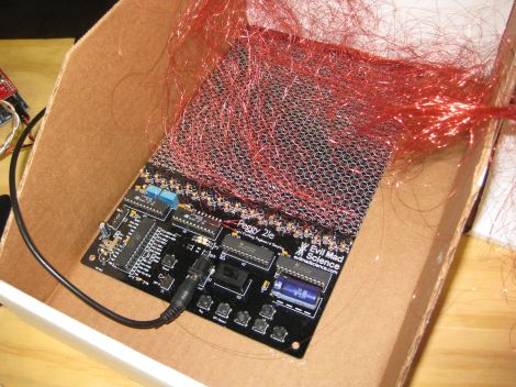
Evil Mad Scientist Laboratories received an email from someone who wanted to hack their Peggy kit. This LED matrix kit has been featured on Hack a Day in the past, and provides hardware to set up a 625 LED matrix.

This user built an external array of LEDs that they wanted to drive with the Peggy hardware. There are a few options for making this happen. The first one is to run wires from each of the 625 LED footprints on the board. Each has an anode and cathode, so that makes for a total of 1250 wires to run. It turns out that people have actually done this with the Peggy in the past, using very fine wire.

EMSL suggests wiring the rows and columns instead. This way, only one wire is needed for each row and column, allowing a 25×25 LED grid to use 50 wires instead of 1250. They also explain how to expand the grid to a 30×20 LED matrix. It’s a good explanation of how the kit works, and how it can be expanded.

Photo [oskay]

Writing On LEDs With A Laser Pointer

After [Ch00f] got his hands on an 8×8 LED display, he didn’t make a 64-pixel video game or VU meter. He made a laser doodler, allowing him to draw on this display with only a laser pointer.

Using LEDs as light sensors is nothing new; [Forrest Mims III] discovered that LEDs can also detect light way back in the late 60s. [Ch00f] played around with this concept before creating a circuit that uses an LED as both a light emitter and sensor that reacts to the ambient brightness.

[Ch00f]’s laser doodler takes this phenomena and applies it to an Adafruit bicolor LED matrix. When a light shines on an individual pixel in the display, the ATMega48 senses the current and turns that pixel on. Since this these pixels have two colors, [Ch00f] used a latch circuit and a button to cycle between what color the ‘Mega writes to the display.

In the video after the break, [Ch00f] shows off his display by having the LEDs light up in response to a laser pointer. It may be a bit small, but we can see a lot of potential for something like this as a gigantic art installation.

Continue reading “Writing On LEDs With A Laser Pointer”

LED Matrix Shield Starts With A Very Loud Snap

We see a lot of LED matrix projects. They’re fun, and you can learn a lot of basic lessons during the build. But this one is out of the ordinary. [Rtty21] built an oddly sized, and sound controlled matrix shield for his Arduino. That’s it right there, the shield is the large chunk of protoboard but you can just see the Arduino peeking up over the top of it.

Now we say oddly sized because a 9×9 matrix doesn’t make much sense with an 8-bit micro controller. There’s no schematic but in the clip after the break he mentions that the columns and rows are driven by a decade counter and shift register and that’s what makes it possible to drive nine bits easily. Also of note on the board is that washer above and to the right of the matrix. It’s a touch-sensitive reset button. But the main control mechanism is a Clapper clone circuit. Just snap your fingers and it turns the project on or off. [Rtty21] based the design on this step-by-step sound input build.

Continue reading “LED Matrix Shield Starts With A Very Loud Snap”

Bring Your Own Name Badge

It used to be that the contents of your pocket protector directly mirrored your geek level. But that just doesn’t cut it in our fast-paced digital age. We think [Jonathan] is headed down the right track though, by creating a scrolling LED name badge which he takes to conventions with him. With the right enclosure this could reach the same geek level as Woz’s watch. There’s a lot packed into the little device, but readability at close range doesn’t look like one the features so make sure you glance at the tag before you approach him for a conversation.

As you can see, the PCB for the project is the same form factor as a landscape ID card. It hosts an 8×5 LED matrix, which meshes nicely with the registers of the MSP430 chip which runs it. He admits that the hardware may not last very long as the chip is multiplexing the display directly, with no resistors or LED drivers for current protection. But there is potential in the design. It uses a rechargeable battery (which we like) and he included a QR code in the board artwork for easy exchange of contact information. We’ve embedded his description of the project after the break. Continue reading “Bring Your Own Name Badge”

Building LED Walls On The Cheap

Around this time last year, [KopfKopfKopfAffe] was enlisted as a set designer and was told to build some sort of light effects for electronic music parties. The budget for the project wasn’t much at 200 Euros, but he did manage to build decent 5×5 RGB LED matrix that is fully controllable by a computer.

[KopfKopfKopfAffe] didn’t have the time or money to wait for manufactured PCBs, so a bunch of perfboard was placed in a CNC mill with a pen to act as a plotter. All the lines that needed soldered were drawn on by the mill, a feat that probably saved hours of looking at the design before committing solder to iron.

A total of five boards were constructed, each one capable of controlling five RGB LEDs. Each board can be dasiy-chained with an RS-232 serial connection for further expansion. The only thing that’s needed to control the matrix is 17 bits that includes an address and RGB color data for each LED. The system only cost about 10 Euros per node, but we think that could be significantly reduced by leaving out the Molex and DB-9 connectors. [Kopf] project turned out very nice, check it out after the break.

Continue reading “Building LED Walls On The Cheap”

Python Maps Mouse Movements On An LED Matrix

[Vinod Stanur] is working with a mouse input and a microcontroller driven LED matrix. The mouse cursor is tracked inside of a window by Python and the resulting coordinates on the LED grid are illuminated. He calls it an LED matrix “Paint Toy” because one of the features he’s included lets the user create pixel art like in MS Paint.

The 10×8 grid of lights is controlled by a PIC 16F877A. This display orientation is perfect for the 8-bit controller, which uses an array of ten bytes to keep track of the pixel data. A computer running his Python application (which uses the Pygame module to track the mouse movements) communicates with the display board via an RF connection. Five bytes plus a stop character make up the communication packet. The first two bytes contain the coordinates of the cursor, the other three bytes contain mouse button status.

As you can see in the demo after the break, the system is very responsive. The mouse can be moved quickly without latency issues, and if the cursor leaves the tracking window it gets picked up right away when it re-enters.

Continue reading “Python Maps Mouse Movements On An LED Matrix”

Rear Window LED Display Gives Other Drivers A Piece Of Your Mind

rear_window_led_matrix

[Gagandeep] was sick and tired of discourteous drivers on the highway, so he decided that he would put together a display to let them know what he thought of their poor driving skills. He planned on putting the display up in the rear window of his car, so he had to ensure that it did not obstruct his view while driving.

He decided that an LED matrix would be the best way for displaying images and text while on the go, so he got busy constructing a 40×16 mesh grid for his rear window. Using a wooden template to get the spacing and positioning just right, he spent several days soldering the 600+ LEDs to one another. He used 74HC595 shift registers to manage the LEDs in groups of 5 columns, while an ATmega AT89C51 was tasked with generating the text and images to be displayed. All of the ICs were deadbugged in place, helping achieve [Gagandeep’s] desire of keeping his view unobstructed.

While we’re not well-versed on the legality of such a display, it looks great when animated. There are plenty of pictures of the grid in various stages of construction as well as videos of it in action in his Picasa album, so be sure to check them out. If you are looking for code or Eagle files, you can find those here.