A small green circuit board with a tiny OLED display

An Oscilloscope Trigger For Vintage Video Processors

Working on retro computers is rarely straightforward, as [ukmaker] recently found out while designing a new display interface. Their oscilloscope was having trouble triggering on the video signal produced by older video circuitry, so they created the Video Trigger for Retrocomputers.

The Texas Instruments TMS9918 video display controller was used across a range of 1980s game consoles and home computers, from the well-known ColecoVision to Texas Instruments’ own TI-99/4. Substantial retro computing heritage notwithstanding, the video output from this chip was (for reasons unknown) not quite compatible with the Hantek DSO1502P oscilloscope. And without a better understanding of the video signal, it was difficult to use the chip with newer TFT displays, being designed for CRT televisions with more forgiving NTSC tolerances.

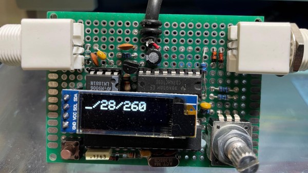
Maybe a different scope would have solved the problem, but [ukmaker] had a feeling that the ‘scope needed an external trigger signal. The Video Trigger project uses a LM1881 sync separator to tease out the horizontal and vertical sync signals from the vintage video chip, with the output piped into an ATmega 328P. Along with a smattering of discrete components, the ATmega aids the user in selecting which line to frame a trigger on, and the slope of the horizontal sync signal to align to. A tiny OLED display makes configuration easy.

If this has piqued your interest, [ukmaker] also has a great write-up over on GitHub with all the gory details. Maybe it will help you in your next vintage computing caper. Having the right tool can make all the difference, like this homebrew logic meter for hobby electronics troubleshooting. Or if you want to know more about the mystical properties of analog NTSC video, we’ve covered that, too.

Adding A SCART Input To A Console VGA Converter

If you’re working with a CGA, EGA, or RGB gaming system this inexpensive board does a great job of converting the signal to VGA so that you can play using a modern display. But what if you have a SCART connector as an output? That’s the situation in which [EverestX] found himself so he hacked in SCART support.

The first step is to source a female SCART connector. He grabbed a coupler off of eBay and cracked it open, yielding two connectors. Now comes the wiring and you may have already noticed that there’s a lot more going on here than the color channels, sync signal, and ground. Technically that’s all you really need to make this happen, but the results will not be good. First off, the sync signal for SCART tends to be rather awful. That’s where the blue breakout board comes into play. [EverestX] used an LM1881 to grab the composite sync (yes, composite sync, not component sync) signal as a feed for the VGA converter. He also added in an audio jack for the sound that is coming through the connector.

Watch A Shop Tour Through The Screen Of An Oscilloscope

[Alan] posted a video tour of his electronics shop, but you’ll be viewing it through the green screen of an oscilloscope. The image above is a video camera filming a scope screen which displays the image of…. an oscilloscope (insert your own Yo Dawg meme here). But first he shares the technique he uses to display composite video on an oscilloscope screen.

The first three minutes of the video after the break are devoted to the video display hack. He starts with a glimpse of the breadboard circuit which takes the composite video signal and provides the necessary X, Y, and Z input signals to the scope to perform like this. He then walks through each portion of the schematic, which is based on an LM1881 video sync separator chip. The horizontal and vertical sync signals are separated by this chip, then filtered to produce ramp voltages for each to drive X and Y. The Z-axis is fed through a simple inverter circuit; Bob’s your uncle and your oscilloscope is now a TV monitor.

Of course this is not the first time this has been done. But we loved [Alan’s] presentation, and thought the shop tour was a fun way to finish off the video.

Continue reading “Watch A Shop Tour Through The Screen Of An Oscilloscope”

Video Experimenter Shield

People always want to do more with less and the Video Experimenter Shield is no exception. Consisting of anĀ LM1881 video sync separator, a handful of passive components, and a stylish PCB in the standard Arduino shield footprint.

The board features simple but useful controls and features, a removable jumper allows you to select a sync source, either from incoming video or the Arduino, a potentiometer to adjust the analog threshold, and there is a convenient signal breakout header.

Software is an enhanced version of the popular TV out library and allows you to start off with video graphics overlay, closed caption decoding, a simple gun game, and basic, but still effective frame capture, and computer vision. Of course, there are all sorts of other fun and amusing experiments that start to pop in mind once you check out a quick demo video after the break.

Continue reading “Video Experimenter Shield”