Coax Stub Filters Demystified

Unless you hold a First Degree RF Wizard rating, chances are good that coax stubs seem a bit baffling to you. They look for all the world like short circuits or open circuits, and yet work their magic and act to match feedline impedances or even as bandpass filters. Pretty interesting behavior from a little piece of coaxial cable.

If you’ve ever wondered how stub filters do their thing, [Fesz] has you covered. His latest video concentrates on practical filters made from quarter-wavelength and half-wavelength stubs. Starting with LTspice simulations, he walks through the different behaviors of open-circuit and short-circuit stubs, as well as what happens when multiple stubs are added to the same feedline. He also covers a nifty online calculator that makes it easy to come up with stub lengths based on things like the velocity factor and characteristic impedance of the coax.

It’s never just about simulations with [Fesz], though, so he presents a real-world stub filter for FM broadcast signals on the 2-meter amateur radio band. The final design required multiple stubs to get 30 dB of attenuation from 88 MHz to 108 MHz, and the filter seemed fairly sensitive to the physical position of the stubs relative to each other. Also, the filter needed a little LC matching circuit to move the passband frequency to the center of the 2-meter band. All the details are in the video below.

It’s pretty cool to see what can be accomplished with just a couple of offcuts of coax. Plus, getting some of the theory behind those funny little features on PCBs that handle microwave frequencies is a nice bonus. This microwave frequency doubler is a nice example of what stubs can do.

Continue reading “Coax Stub Filters Demystified”

Antenna Tuning For GHz Frequencies

Antenna tuning at HF frequencies is something that radio amateurs learn as part of their licence exam, and then hone over their time operating. A few basic instruments and an LC network antenna tuner in a box are all that is required, and everything from a bit of wet string to ten thousand dollars worth of commercial antenna can be loaded up and used to work the world. When a move is made into the gigahertz range though it becomes a little more difficult. The same principles apply, but the variables of antenna design are much harder to get right and a par of wire snippers and an antenna tuner is no longer enough. With a plethora of GHz-range electronic devices surrounding us there has been more than one engineer sucked into a well of doom by imagining that their antenna design would be an easy task.

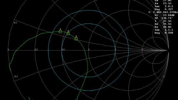
An article from Baseapp then makes for very interesting reading. Titled “Antenna tuning for beginners“, it approaches the subject from the perspective of miniature GHz antennas for IoT devices and the like. We’re taken through the basics and have a look at different types of antennas and connectors, before being introduced to a Vector Network Analyser, or VNA. Here is where some of the Black Art of high frequency RF design is laid bare, with everything explained through a series of use cases.

Though many of you will at some time or other work with these frequencies it’s very likely that few of you will do this kind of design exercise. It’s hard work, and there are so many ready-made RF modules upon which an engineer has already done the difficult part for you. But it does no harm to know something about it, so it’s very much worth taking a look at this piece.

It’s an area we’ve ventured into before, at a Superconference a few years ago [Michael Ossmann] gave us a fundamental introduction to RF design.

Pi Network Attenuators: Impedance Matching For The Strong Of Signal

If you catch a grizzled old radio amateur propping up the bar in the small hours, you will probably receive the gravelly-voiced Wisdom of the Ancients on impedance matching, antenna tuners, and LC networks. Impedance at RF, you will learn, is a Dark Art, for which you need a lifetime of experience to master. And presumably a taste for bourbon and branch water, to preserve the noir aesthetic.

It’s not strictly true, of course, but it is the case that impedance matching at RF with an LC network can be something of a pain. You will calculate and simulate, but you will always find a host of other environmental factors getting in the way when it comes down to achieving a match. Much tweaking of values ensues, and probably a bit of estimating just how bad a particular voltage standing wave ratio (VSWR) can be for your circuit.

Continue reading “Pi Network Attenuators: Impedance Matching For The Strong Of Signal”