A DIY Atomic Force Microscope

AFM

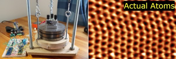
For looking at really small stuff, an optical microscope will only go so far. Looking at things at the nanometer level, though, usually requires some sort of electron microscope, with all the hassle of vacuum chambers and high voltages. There is another way to investigate the domain of the very small: an atomic force microscope. Unlike their electron spewing brothers, they don’t require high voltages or hard vacuums. They can also be built for about $1000, as [whoand] over on the Instructables shows us.

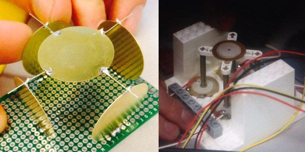
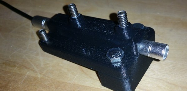
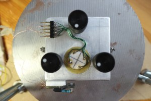
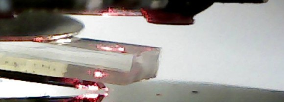
Instead of shooting light or electrons at an object and picking up the reflections, an atomic force microscope drags a very, very tiny stylus across an object. This stylus is attached to a probe that will reflect laser light off of it into a photosensor, eventually rendering an image on a display. [whoand] is using a laser diode and pickup unit from a DVD-ROM drive for the optical pickup unit, a frame made from soldered together PCBs, and a few piezos to vibrate the probe.

The probes themselves are incredible pieces of engineering with a tip size of a few nanometers. They’re consumable, and expensive, ranging from $20 to $500 per probe. Still, with these probes, [whoand] can look at the pits in a CD or DVD, measure the surface of an eraser, or check out the particulate matter floating around in the atmosphere in Beijing.

Thanks [Rob] for the tip.

Building An LED Source For A Fiber Optic Ring Light

[Peter] has finished up his fiber optic microscope light source. When we last visited [Peter] he created a dimmer circuit for a 10 watt LED. That LED driver has now found its final home in [Peter’s] “Franken-ebay scope”, a stereo microscope built from parts he acquired over several years. Stereo microscopes scopes like these are invaluable for working on surface mount parts, or inspecting PCB problems. [Peter] had the fiber optic ring and whip, but no light source. The original source would have been a 150W Halogen lamp. The 10 watt led and driver circuit was a great replacement, but he needed way to interface the LED to the fiber whip. Keeping the entire system cool would be a good idea too.

This was no problem for [Peter], as he has access to a milling machine. He used an old CPU heat sink from his junk box as the base of the light source. The heat sink was drilled and tapped for the LED. The next problem was the actual fiber whip interface. For this, [Peter] milled a custom block from aluminum bar stock. The finished assembly holds the LED, driver, and the fiber whip. A sheet metal bracket allows the entire assembly to be mounted on the microscope’s post.  We have to admit, if we were in [Peter’s] place, we would have gone with a cheap LED ring light. However, the end result is a very clean setup that throws a ton of light onto whatever [Peter] needs magnified.

Continue reading “Building An LED Source For A Fiber Optic Ring Light”

Use Your Smartphone As A Microscope For Less Than $10

FY4TBHSHMMFBB4V.LARGE[Yoshinok] recently posted an Instructable on doing a $10 smartphone-to-microscope conversion. The hack isn’t so much a conversion as just a handy jig, but it’s still interesting. The basic idea is to set up a platform for the slides, and to mount the smartphone directly above. The trick, and the reason this can be called a microscope, is that [Yoshinok] embeds the lens from a cheap laser pointer into the smartphone holder. He is able to get 40x optical magnification with the lens, and even though it sacrifices quality, he uses the built-in digital zoom to get up to 175x magnification.

By itself, you could use this with a light source to magnify 3D objects. [Yoshinok] demonstrates this with a dime. But since the slide holder is made of clear acrylic, he mounted a cheap LED flashlight in the base to serve as through-sample lighting. Using this setup, he was able to observe the process of plasmolysis.

If you have kids, this is certainly a project to do with them, but we can’t help but think it will be useful for non-parents alike. This sort of magnification is good enough for simple lab experiments, and given that most Hack-a-Day readers have these parts lying around, we figure the cost is closer to $0. If you give it a try, let us know your results in the comments!

Continue reading “Use Your Smartphone As A Microscope For Less Than $10”

Microscope Ring Light With A Number Of Different Features

microscope-ring-light

Microscopes magnify light. It makes sense that having more light reflecting off of the subject will result in a better magnified image. And so we come to Aziz! Light! It’s [Steve’s] LED light ring for a stereo microscope. It’s also a shout out to one of our favorite Sci-Fi movies.

He’s not messing around with this microscope. We’ve already seen his custom stand and camera add-on. This is no exception. The device uses a fab-house PCB which he designed. It boasts a dual-ring of white LEDs. But the controls don’t simply stop with on and off. He’s included two rotary encoders, three momentary push switches, and three LEDs as a user interface. This is all shown off in his demo video after the break.

An ATtiny1634 is responsible for controlling the device. When turned on it gently ramps the light up to medium brightness. This can be adjusted with one of the rotary encoders. If there are shadows or other issues one of the push buttons can be used to change the mode, allowing a rotary encoder to select different lighting patterns to remedy the situation. There are even different setting for driving the inner and outer rings of LEDs.

We haven’t worked with any high-end optical microscopy. Are these features something that is available on commercial hardware, or is [Steve] forging new ground here?

Continue reading “Microscope Ring Light With A Number Of Different Features”

Camera Adapter For A Microscope

camera-adapter-for-stereo-microscope

[Steve] really has a nice microscope setup in his lab now that he built a video camera adapter for his stereo microscope. The image above shows the magnified view of the circuit board on the LCD screen behind it. This lets him work without needing to be in position to look through the eye pieces. The hack is a perfect complement to the custom stand he fabricated for the scope.

The camera attachment can be seen attached to the right lens of the scope. It’s an old security camera which he already had on hand. The stock lens wasn’t going to bring the picture into focus, but he had some different optics on hand and one of them fit the bill perfectly. The rest of the project involves fabricating the adapter ring on his lathe. It slips perfectly over the eyepiece and even allows him a bit of adjustment to get the focal length right. The best view of this is shown off in the video after the break.

Continue reading “Camera Adapter For A Microscope”

The Perils Of Buying A Stereo Microscope Without A Stand

scope

[Steve] has wanted a stereo microscope in his lab for years now. Since his eyesight is becoming progressively worse, he figured it was time to look around on ebay and see what he could dig up. He ended up buying a very cheap microscope without a stand, figuring he could build one rather easily. Well, the articulated stand was rather easy to put together, but it did take a whole lot of time to build.

The main goal of [Steve]’s project was to have his microscope at the end of an articulated arm. With this setup, he could easily tuck the ‘scope against the back of his workbench when not in use and easily bring it out when necessary. This meant building a custom arm, though, and in the building process [Steve] used just about every machine tool he had at his disposal.

The end result is a fully articulated arm that can be moved to just about any point on his workbench and adjusted up and down for those really weird project. [Steve] says this may be a great introduction to home powder coating, and he really should build a small LED light source, but we’re loving the project so far.

Continue reading “The Perils Of Buying A Stereo Microscope Without A Stand”

Reverse Engineering Salvaged Part Footprints

reverse-engineering-component-footprints

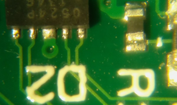
So you just pulled a fancy component off of a board from some broken electronics and you want to use it in your own project. What if the data sheet you found for it doesn’t include measurements for the footprint? Sure, you could pull out your digital calipers, but look at the measurements in the image above. How the heck are you supposed to accurately measure that? [Steve] found an easy answer for this problem. He uses microscope software to process an image of the board.

One common task when working with a microscope is measuring the items which are being viewed under magnification. [Steve] harnessed the power of a piece of free software called MiCam. One of its features is the ability to select an area of the photograph so serve as the measuring stick. To get the labels seen in the image above he selected the left and right edges of the board as the legend. He used his digital calipers to get a precise measurement of this area, then let the software automatically calculate the rest of the distances which he selected with his cursor.

MiCam is written for Windows machines. If you know of Linux or OSX alternatives please let us know in the comments.