Copying Objects In 3D

photocopier

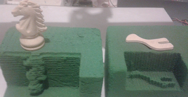
[Pulse 9] sent in a very interesting project he just finished up at an internship. It’s a 3D photocopier that scans an object and then mills said object into floral foam.

The copier is made out of material [Pulse] found sitting around – PVC, drawer slides for the X and Y axes, acrylic for the structure, and broken printer parts for the Z axis.

To scan an object, [Pulse] puts an object down on the bed and scans it with a laser and webcam. The images recorded on the camera are fed into MATLAB. The output from MATLAB is sent over serial to a custom board containing a PIC18F4620 that controls the axis motors. The spindle for this floral foam router is a simple drill; one layer at a time, the drill mills out the unneeded foam which can be sucked up by a vacuum when the object is complete.

Below you’ll find [Pulse]’s demo of his photocopier and a piece the local news did on the project. If anyone is willing to translate that story, feel free to do so in the comments.

Continue reading “Copying Objects In 3D”

Milled Water Bottle Rocket Launcher Pushes Plastic Containers To Their Limit

water-bottle-rocket-launcher

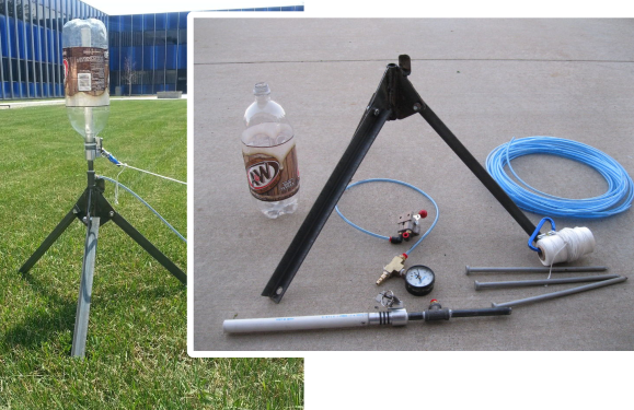
Building this launcher is simple if you already have a mill. It does a remarkable job of pressurizing and launching soda bottles which are partially filled with water. The main component of this is a triple-gasket stopper with a quick release.

The problem with a lot of these water bottle rocket projects is that they leak where the bottle meets the launcher. In most cases this is a good thing as it’s almost impossible to build up enough pressure to cause the bottle to fail. This system has no such built-in safety mechanism, which is why the test launch below is conducted from a safe distance. After seating the partially filled bottle on the launch platform it’s pressurized to around 100 PSI at which point a yank on the string lets it fly.

Most of the time we look on these as casual projects. But we figure this one is much more suited for a rocket club or hackerspace event.

Continue reading “Milled Water Bottle Rocket Launcher Pushes Plastic Containers To Their Limit”

Machining Beer Can Solder Stencils

This is a solder paste stencil machined from a beer can. [Simon Ludborzs] spent quite a bit of time dialing in his process to get to this point. Note the nice crisp edges of the openings. That’s a big change from his first attempt.

When looking for a way to make his own stencils he considered two options: plastic and aluminum. He produced both (more about the plastic stencil and his reflow process is discussed in this post). Plastic is a bit easier to work with since it lays flat. But it proves to be too thick. After applying paste with a squeegee there’s way too much solder on the pads. Aluminum beverage can walls are much thinner, depositing less paste.

We’ve seen soda cans used in the past, but they were produced through an etching process. [Simon] cut these holes using a CNC mill. This required a bit of futzing to figure out the right settings. For instance, he used Altium to produce CAM files from his circuit design. But the program is set up to mill the outside of traces, resulting in openings that are too large. He fixed this by setting the pasted expansion rule in the program to a negative value. The other advantage to using a mill is that he can cut precision tooling holes to ensure proper alignment. You can see them in the upper corners of this image.

Quadruped Walks Of Four Legs, Rolls On Four Treads

tracked-quadruped-robot

This robot doesn’t know if it’s a walker or a tank. It’s the brain-child of [Marc Hamende] who works as a mechanical engineer by day and mad roboticist at night. The best place to find full details is by digging into the long thread he’s been posting to for about six weeks. It will give you a pretty good snapshot of his approach, starting with SolidWorks renderings of the project, and adding in assembled components as he brings the project together.

The mechanism for each foot is fascinating. He milled the white pieces which stack together to encapsulate the motor that runs the treads. These assemblies pivot to bring the metal rod serving as a walking foot in contact with the ground. But they also make it possible to adjust the treads to deal with rough terrain. A Propeller chip drives the device, with an Xbee module to communicate with the controller.

Don’t miss the video after the break. You’ll hear some skidding as it makes turns, but [Marc] plans to add code to adjust motor speed in order to compensate for the inside/outside differential issues. He’s also posted an image album over at Flickr.

Continue reading “Quadruped Walks Of Four Legs, Rolls On Four Treads”

Humble Beginnings Of A Home Automation Project

humble-beginnings-to-a-home-automation-project

This board is the start of [Steven Pearson’s] quest to automate his home. The module will be used to prototype the rest of the project. Right now it uses an ATmega328 chip running the Arduino bootloader. This connects to one mechanical relay which we would wager is mains rated. The module will be controlled wirelessly via the wireless module seen in the foreground. That is a nRF24L01 board which he chose because of it’s bargain basement price tag of around $1.50.

There is much room for expansion in the system. You can see that a light-dependent resistor has been added to some of the microcontroller’s breakout pins. We would guess that [Steven] will use the hardware to develop for many different functions and will design more task-specific modules as the project progresses.

If you’re a fan of PCB milling and population you won’t want to miss the video after the break. [Steve] posted a fast-motion video of the entire process.

Continue reading “Humble Beginnings Of A Home Automation Project”

Through Hole Plating And Milling At Home

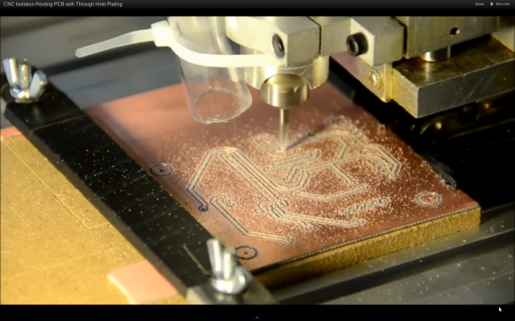
Here’s a PCB fabrication process that makes us envious. It’s pretty darn close to fab-house quality at home. [Cpirius] is using a CNC mill and through hole plating technique to produce his double-sided circuit boards.

The video embedded after the break shows one board from start to finish. It begins with the mill drilling holes through some double-sided copper clad stock. Once the millings have been cleaned off the holes are coated with a mixture of waterproof ink and carbon. This prepares them for plating by making the holes themselves conductive. The board is then run through an electroplating process based on this guide.

Possibly the most interesting part of the process starts 52 seconds into the clip. The mill uses a conductive probe to generate a height map of the entire board. This allows it to vary the routing depth for perfectly cut isolation traces. That final routing process is pictured above.

Continue reading “Through Hole Plating And Milling At Home”

Milling A Motorcycle Engine

Real motorcycle enthusiasts design and mill their own engines. Well, perhaps that’s an overstatement. Certainly it takes to more obsession than enthusiasm to go to these lengths. But this gentleman’s modifications started out simple enough, and managed to make it to the most extreme of hardware fabrications.

The used bike came with a modified camshaft that seemed like a botched job. As he got further into tuning up engine performance the prospect of just replacing the entire thing with his own design started to grow. Using a manually operated milling machine he cut his own molds for the new cylinder head out of wood and sent them off to be forged out of aluminum. They come back in rough shape but he just “filed the cast without mercy” and machined the tolerances to his specifications. Apparently the first test ride had him a bit nervous — he also milled his own brakes for the bike. But after a few times around the block he gained confidence with his work.

[Thanks Carlos]