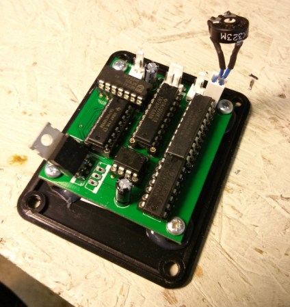
[James] recently finished up a gigantic seven segment display for Nottingham Hackerspace, and although it looks great, the display isn’t the interesting part. The PWM dimmer control implemented in logic is the true head-turner. That’s right: this is done without a programmable controller.
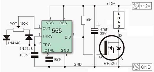
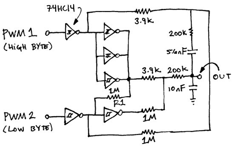
Unsatisfied with the lack of difficulty he faced when slapping together the rest of the electronics, [James] was determined to complicate the auto-dimmer by foregoing all sensible routes. He started by building an 8-bit timer made from a 555 timer fed into a 12-bit 4040 counter. He then used an 8-bit ADC IC to read a photoresistor. The outputs from both the ADC and from the scratch-built 8-bit timer plug into an 8-bit comparator; If the values match, the comparator outputs LOW for a single clock period.
Though this set the groundwork for PWM control, [James] had to add a couple of additional logic gates into the mix to nail everything down. You can find a diagram and the details behind flip-flopping out a duty cycle on his project blog. Clever builds like this one are a rarity when a few lines of code and a microcontroller can give you numerous shortcuts. [James] doesn’t recommend that you over-engineer your PWM controller, but we’re glad he did. Meanwhile, Moore’s Law marches on; check out what people are doing with Low-Energy Bluetooth these days.