[Quinn Dunki]’s awesome 6502-based computer is coming right along, and she decided it’s time to add one of the most important features found in the 80s microcomputers she’s inspired by – gamepads.
There were two ways of implementing gamepads back in the 80s. The Apple II analog joysticks used a potentiometer for each joystick axis along with a 556 timer chip to convert the resistance of a pot into a digital value. Analog controls are awesome, but a lot of hardware is required. The other option is the Atari/Commodore joystick that uses buttons for each direction. Surprisingly, these joysticks are inordinately expensive on the vintage market but a similar hardware setup – NES gamepads – are common, dirt cheap, and extremely well documented.
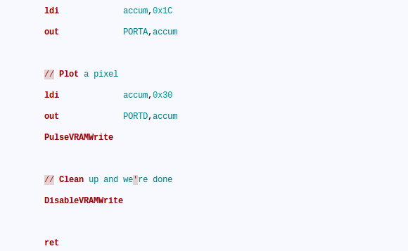
[Quinn] wrote a few bits of 6502 assembly to read these Nintendo controllers with Veronica’s 6522 VIA with the help of an ATMega168, and then everything went to crap.
In testing her setup, she found that sometimes the data line from the controller would be out of sync with the clock line. For four months, [Quinn] struggled with this problem and came up with one of two possible problems: either her circuit was bad, or the 6522 chip in Veronica was bad. You can guess which option is correct, but you’ll probably be wrong.
The problem turned out to be the 6522. It turns out this chip has a bug when it’s used with an external clock. In 40 years of production this hasn’t been fixed, but luckily 6502 wizard [Garth Wilson] has a solution for this problem: just add a flip-flop and everything’s kosher. If only this bug were mentioned in the current datasheets…
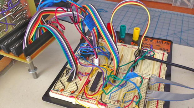
Now Veronica has two NES controller inputs and the requisite circuitry to make everything work. Video evidence below.
Continue reading “Veronica Gets A Pair Of Gamepads And A Bugged Chip”