For this year’s Hackaday Prize, we’re doing something special. We’re introducing achievements for Prize projects. Think of them as merit badges. If your Hackaday Prize project has multiple parts that come together into one unified, awesome whole, you get the Voltron achievement. If you’ve built a musical instrument that unexpectedly blows everyone’s minds, you get the Diva Plavalaguna Achievement. A select few entries will earn the Pickle Rick achievement. What’s this? It’s a jaw-dropping build that makes you shake your head in the totality of engineering perfection.
Here’s a project that nails this achievement. It’s a homebrew computer, made out of relays, that runs a custom instruction set. It’s built on Brainf*ck. It is, by far, the most absurd and amazing homebrew computer you’ve ever seen.
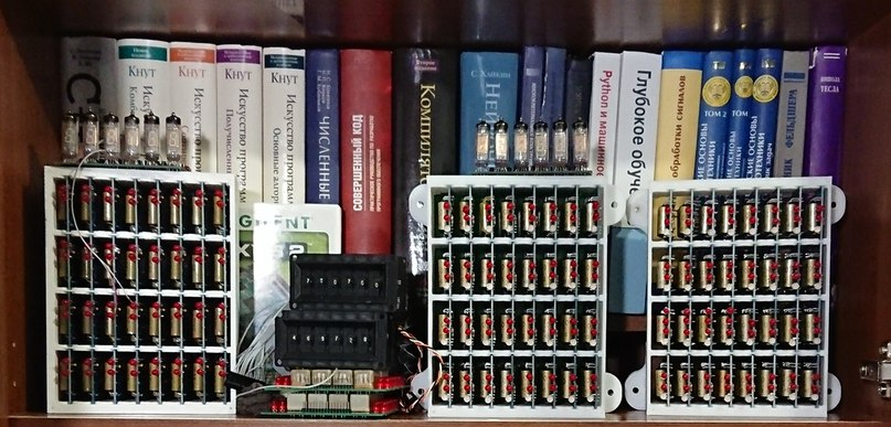
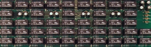
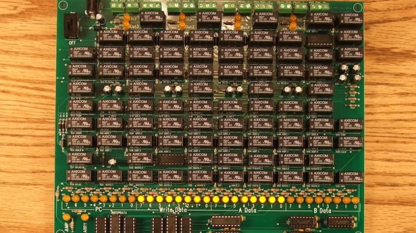
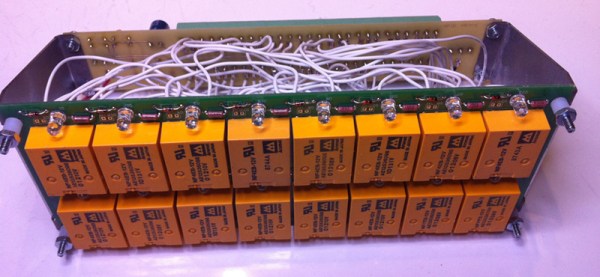
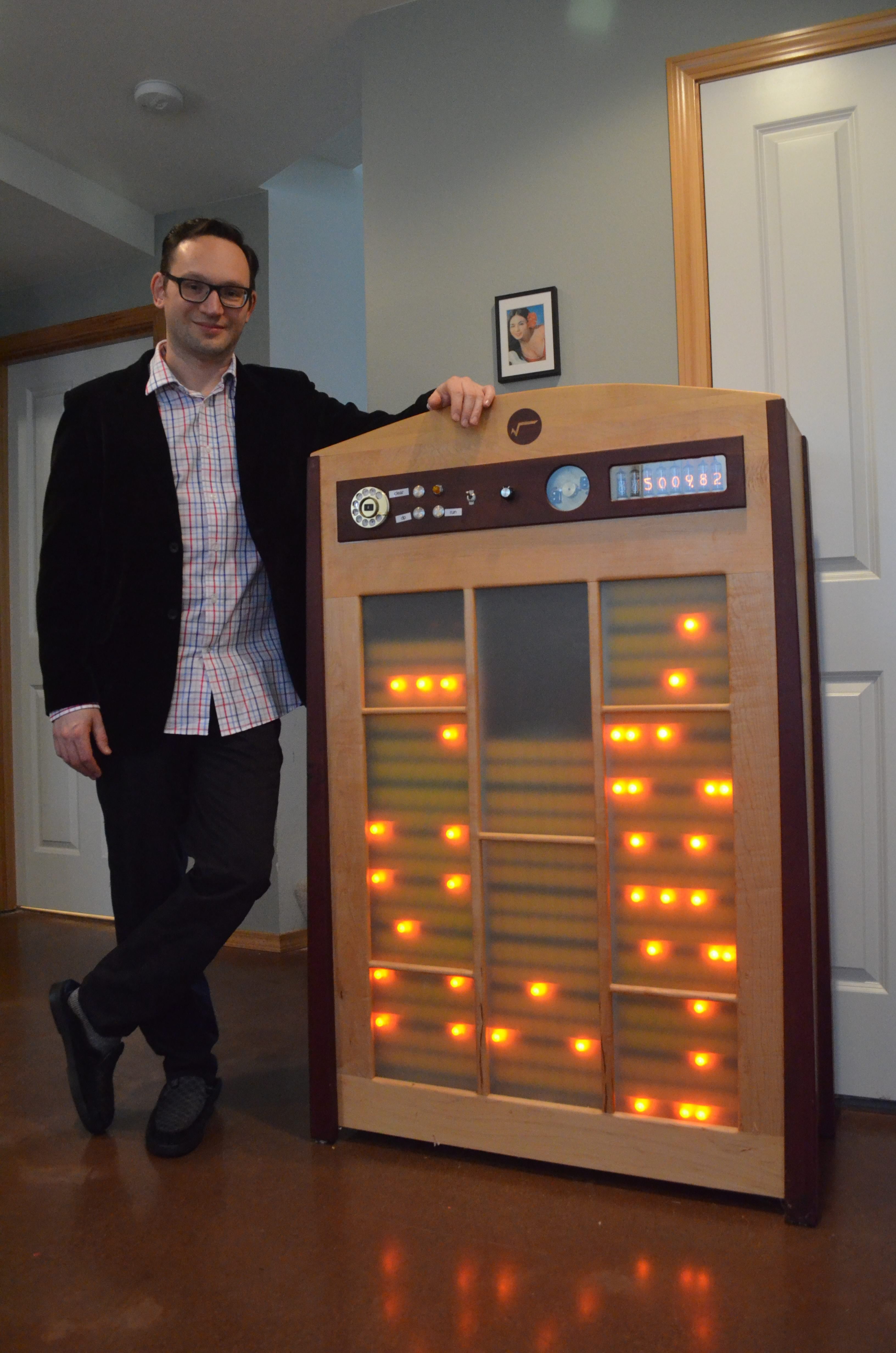
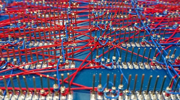
First, the hardware. This CPU is built out of about 800 Soviet reed relays, RES64, RES55, and RES-43 relays, if you want some part numbers. These relays are mounted on logic cards connected to a backplane. Each backplane consists of thirty-two of these cards, and it takes two backplanes to build up a 16-bit full adder. The 16-bit instruction pointer and 16-bit address pointer each fit on half a backplane.
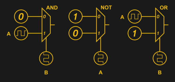
Moving up one level, the instruction set for this computer is based on Brainf*ck, with a few additions. The ‘+’ instruction adds to the current value, the ‘>’ instruction still increases the current memory address, but there are a few new instructions that make this CPU not an interminable world of suffering. There’s now a ‘write current data value to register’ commands, and logical XOR instructions.
Have relay-based computers been done before? Yes, and so have Brainf*ck ISAs. The combination is rarely seen, and we’ve never seen one that performs this well. Below, you can see a video of this computer counting at 500 operations per second (or 500 Hz from a frequency counter). This is really unimaginable with any other relay computer we’ve seen, and it’s all thanks to those really tiny Soviet tubes. If you want a Hackaday Prize project that’s jaw-dropping, here you go.
Continue reading “Because Building A Relay Computer Isn’t Hard Enough”