If you are someone whose interests lie in the field of RF, you won’t need telling about the endless field of new possibilities opened up by the advent of affordable software defined radio technology. If you are a designer or constructor it might be tempting to believe that these radios could reduce some of the problems facing an RF design engineer. After all, that tricky signal processing work has been moved into code, so the RF engineer’s only remaining job should be to fill the not-so-huge gap between antenna and ADC or DAC.
In some cases this is true. If you are designing an SDR front end for a relatively narrow band of frequencies, perhaps a single frequency allocation such as an amateur band, the challenges are largely the same as those you’d find in the front end of a traditional radio. The simplest SDRs are thus well within the abilities of a home constructor, for example converting a below-100kHz-wide segment of radio spectrum to the below-100kHz baseband audio bandwidth of a decent quality computer sound card which serves as both ADC and DAC. You will only need to design one set of not-very-wide filters, and the integrated circuits you’ll use will not be particularly exotic.
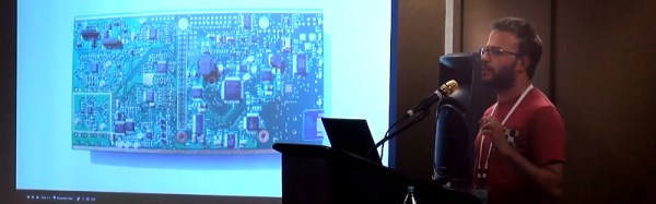
But what happens if the SDR you are designing is not a simple narrow-band device? [Chris Testa, KD2BMH] delivered a talk at this year’s Dayton Hamvention looking at some of the mistakes he made and pitfalls he encountered over the last few years of work on his 50MHz to 1GHz-bandwidth Whitebox handheld SDR project. It’s not a FoTW in the traditional sense in that it is not a single ignominious fail, instead it is a candid and fascinating examination of so many of the wrong turnings a would-be RF engineer can make.
The video of his talk can be found below the break, courtesy of Ham Radio Now. [Chris]’s talk is part of a longer presentation after [Bruce Perens, K6BP] who some of you may recognise from his activities when he’s not talking about digital voice and SDRs. We’re jumping in at about the 34 minute mark to catch [Chris], but [Bruce]’s talk is almost worth an article in itself..
Continue reading “Fail Of The Week: The Pitfalls Of Designing A Wideband Radio” →