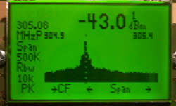
Hackers everywhere are having a lot of fun with SDR – as is obvious from the amount of related posts here on Hackaday. And why not, the hardware is cheap and easily available. There are all kinds of software tools you can use to dig in and explore, such as SDR# , Audacity, HDSDR and so on. [illias] has been following SDR projects for a while, which piqued his interest enough for him to start playing with it. He didn’t have any real project in mind so he focused on studying the methodology and the tools available for analyzing 433MHz RF transmission. He describes the process of using MATLAB to recover the transmissions being received by the SDR
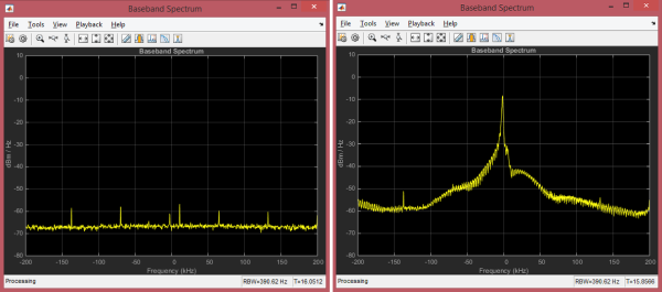
He started off by studying the existing tools available to uncover the details of the protocol. The test rig uses an Arduino UNO with the rc-switch library to transmit via a common and inexpensive 433MHz module. SDR# is used to record the transmissions and Audacity allows [illias] to visualize the resulting .wav files. But the really interesting part is where he documents the signal analysis using MATLAB.
He used the RTL-SDR package in conjunction with the Communications System Toolbox to perform spectrum analysis, noise filtering and envelope extraction. MATLAB may not be the easiest to work with, nor the cheapest, but its powerful features and the fact that it can easily read data coming from the SDR makes it an interesting tool. For the full skinny on what this SDR thing is all about, check out Why you should care about Software Defined Radio.


 The project featured in this post is


