3D printed rotary table

Bearing Witness: Measuring The Wobbles In Rotary Build

3D printing has simplified the creation of many things, but part of making something is knowing just how much you can rely on it. On the [BubsBuilds] YouTube channel, he built a cheap rotary table and then walked through the process of measuring the error inherent in any rotating system.

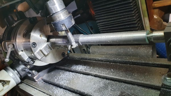
Starting with a commercial rotary table, [BubsBuilds] decided he wanted a rotary stage that was both lighter and had provisions for motorized movement. Most of the rotary build is 3D printed, with the large housing and table made from PETG, and the geared hub and worm gear printed on a resin printer. The bearings used to support the worm gear are common skateboard bearings. There is also a commercial thrust bearing and 49 larger 9.5 mm ball bearings supporting the rotating tabletop.

There are three different types of runout to be measured on a rotating stage: axial, radial, and angular. Axial runout is fairly straightforward to discern by measuring the vertical variation of the table as it rotates. Radial runout measures how true the rotation is around the center of the table. Angular runout measures how level the table stays throughout its range. Since these two runouts are tied to each other, [BubsBuilds] showed how you can take measurements at two different heights and use trigonometry to obtain both your radial and angular runout

This is a great walk-through of how to approach measuring and characterizing a system that has multiple variables at play. Be sure to check out some of the other cool rotary tables we’ve featured.

Continue reading “Bearing Witness: Measuring The Wobbles In Rotary Build”

Tactical Build Makes Machining Splined Shaft A Snap

Quick, what’s 360 divided by 23? It’s easy enough to get the answer, of course, but if you need to machine a feature every 15.652 degrees around a shaft, how exactly would you accomplish that? There are a number of ways, but they all involve some degree of machining wizardry. Or, you can just make the problem go away with a little automation.

The story behind [Tony Goacher]’s Rotary Table Buddy begins with some ATV tracks he got off AliExpress. His idea is to build a specialty electric vehicle for next year’s EMF Camp. The tracks require a splined shaft to drive them, which would need to be custom-made on a milling machine. A rotary table with a dividing plate — not as fancy as this one, of course –is usually the answer, but [Tony] was a little worried about getting everything set up correctly, so he embarked on a tactical automation solution to the problem.

An RP2040 provided the brains of the project, while a NEMA 23 stepper provides the brawn. [Tony] whipped up a quick PCB and 3D printed a case for the microcontroller, a stepper driver, an LCD display, and a few buttons. He 3D printed an adapter and a shaft coupler to mount the stepper motor to a rotary table. From there it was just a matter of coming up with a bit of code to run everything.

There’s a brief video in [Tony]’s blog post that shows Rotary Table Buddy in action, indexing to the next position after cutting one of the 23 splines. He says it took about ten minutes to cut each spline using this setup, which probably makes to total cutting time far less than the amount of time invested in the tool. But that’s hardly the point, and besides, now he’s set up for all kinds of machining operations in the future.

And we sure hope we hear about the EMF Camp build, too.

Turning And Burning With A CNC Pyrography Machine

With CNC machines, generally the more axes the better. Three-axis machines with a vertical quill over a rectangular workspace are de rigueur, and adding an axis or two can really step up the flexibility of a machine. But can only two axes be of any use? Sure can, as witnessed by this two-axis CNC wood burning machine.

As [tuckershannon] tells the tale, this was a newbie build aided by the local hackerspace. Axis one is a rotary table of laser-cut wood gears powered by a stepper. Axis two is just a stepper and lead screw sitting on a couple of blocks of wood. A Raspberry Pi under the hood controls the motors and cycles the pyrography pen on and off as it scans across a piece of wood on the rotary table, burning a spiral pattern that makes for some interesting art. Hats off to [tuckershannon] for figuring out the math needed to adapt to the changing speed of the pen over the wood as the diameter gets bigger.

We love this build, can’t help but wonder if some clever gearing could eliminate the need for the second stepper. And perhaps an upgrade from the standard resistive wood burner to an arc lighter pyrography pen would improve resolution. Still, it’s hard to argue with results, and this is a great hack.

[via r/raspberrypi]

Thanks to [Liz] for the tip!