Iron Nitrides: Powerful Magnets Without The Rare Earth Elements

Since their relatively recent appearance on the commercial scene, rare-earth magnets have made quite a splash in the public imagination. The amount of magnetic energy packed into these tiny, shiny objects has led to technological leaps that weren’t possible before they came along, like the vibration motors in cell phones, or the tiny speakers in earbuds and hearing aids. And that’s not to mention the motors in electric vehicles and the generators in wind turbines, along with countless medical, military, and scientific uses.

These advances come at a cost, though, as the rare earth elements needed to make them are getting harder to come by. It’s not that rare earth elements like neodymium are all that rare geologically; rather, deposits are unevenly distributed, making it easy for the metals to become pawns in a neverending geopolitical chess game. What’s more, extracting them from their ores is a tricky business in an era of increased sensitivity to environmental considerations.

Luckily, there’s more than one way to make a magnet, and it may soon be possible to build permanent magnets as strong as neodymium magnets, but without any rare earth metals. In fact, the only thing needed to make them is iron and nitrogen, plus an understanding of crystal structure and some engineering ingenuity.

Continue reading “Iron Nitrides: Powerful Magnets Without The Rare Earth Elements”

The Imperfect Bipolar Transistor

We like to pretend that our circuit elements are perfect because, honestly, it makes life easier and it often doesn’t matter much in practice. For a normal design, the fact that a foot of wire has a tiny bit of resistance or that our capacitor value might be off by 10% doesn’t make much difference. One place that we really bury our heads in the sand, though, is when we use bipolar transistors as switches. A perfect switch would have 0 volts across it when it is actuated. A real switch won’t quite get there, but it will be doggone close. But a bipolar transistor in saturation won’t be really all the way on. [The Offset Volt] looks at how a bipolar transistor switches and why the voltage across it at saturation is a few tenths of a volt. You can see the video below.

To understand it, you’ll need a little bit of math and some understanding of the construction of transistors. The idea of using a transistor as a switch is that the transistor is saturated — that is, increasing base current doesn’t make much change in the collector current. While it isn’t perfect, it is good enough to switch a relay or do other common switching tasks.

Continue reading “The Imperfect Bipolar Transistor”

Keyboard Switch Is Really A Transformer

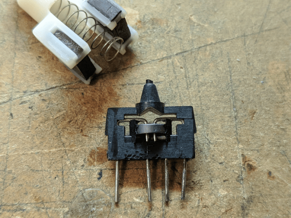
We don’t know why [TubeTime] decided to show off this oddball keyboard switch as a series of Twitter posts, but we were glad to see them somewhere. At first, the switch looks pretty conventional. But as the pictures reveal the insides, you’ll notice something unusual: a ferrite toroid! These switches operate as a transformer and are known as magnetic valve switches.

The switches have two sets of two pins — one set for the primary and one for the secondary of the transformer wound around the ferrite core. That transformer remains stationary, but a pair of permanent magnets move. When the key is up, the magnets are close to the core and cause the transformer to saturate, so there is little or no output at the secondary. When you depress the key, the magnet moves away from the core, allowing the signal to pass through the transformer. What that means is there is no mechanical contact, which is good for switch life. It is also important in environments where a small spark could cause an explosion. You can watch a video about a keyboard that used those switches, below.

Continue reading “Keyboard Switch Is Really A Transformer”

Making An Inductor Saturation Current Tester

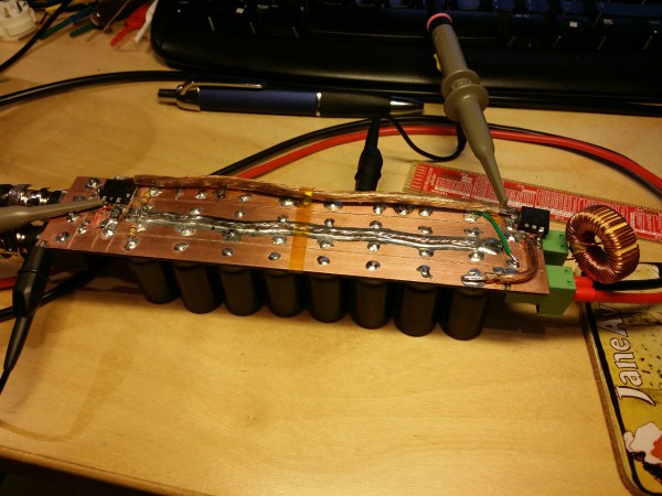
[Kalle] tipped us about a quick project he made over a couple of evenings: an inductor saturation current tester. All the components used for it were salvaged from a beefy telecom power supply, which allows the tester to run currents up to 100A during 30us in the inductors to be characterized.

Knowing the limits of an inductor is very convenient when designing Switch Mode Power Supplies (SMPS) as an inadequate choice may result in very poor performances under high loads. [Kalle]’s tester simply consists in a N-Mosfet switching power through a load while a shunt allows current measurements. The saturation point is then found when the current going through the inductor suddenly peaks. As you can see from the picture above, 16 4700uF electrolytic caps are used to compensate for the sudden voltage drop when the Mosfet is activated. A video of the system in action is embedded after the break.

Continue reading “Making An Inductor Saturation Current Tester”