Dig Into The Apple Device Design Guide

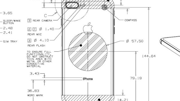
Millions of people worldwide have just added new Apple gadgets to their lives thanks to the annual end of December consumerism event. Those who are also Hackaday readers are likely devising cool projects incorporating their new toys. This is a good time to remind everybody that Apple publishes information useful for such endeavors: the Accessory Design Guidelines for Apple Devices (PDF).

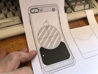
This comes to our attention because [Pablo] referenced it to modify an air vent magnet mount. The metal parts of a magnetic mount interferes with wireless charging. [Pablo] looked in Apple’s design guide and found exactly where he needed to cut the metal plate in order to avoid blocking the wireless charging coil of his iPhone 8 Plus. What could have been a tedious reverse-engineering project was greatly simplified by Reading The… Fine… Manual.
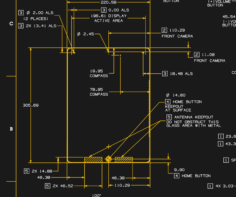
Apple has earned its reputation for hacker unfriendliness with nonstandard fasteners and liberal use of glue. And that’s even before we start talking about their digital barriers. But if your project doesn’t involve voiding the warranty, their design guide eliminates tedious dimension measuring so you can focus on the fun parts.

Dimensioned drawing of Apple iPad Pro

This guide is packed full of dimensioned drawings. A cursory review shows that they look pretty good and aren’t terrible at all. Button, connector, camera, and other external locations make this an indispensable tool for anyone planning to mill or print an interface for any of Apple’s hardware.

So let’s see those projects! Maybe a better M&M sorter. Perhaps a time-lapse machine. Or cure your car’s Tesla envy and put a well-integrated iPad into the dashboard.

Hacking A DVD Recorder

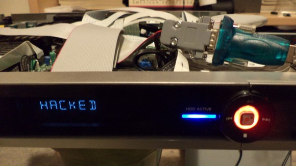
Hacked DVD Recorder

[w00fer] wanted to see if any modifications to a DVD Recorder were possible. Initially, the goal was to upgrade the internal hard drive for additional storage. However, after cracking open a DVDR3570H and finding a service port, he decided to look a bit deeper.

Connecting an RS232 to USB converter to the service port resulted in garbled data. It turned out that the port was using TTL signal levels instead of RS232 levels. This was solved by building a converter using the MAX232 converter IC.

With the converter in place, the service menu appeared. It performs some tests and spits out the results when the device is booted. After that, it sits at a prompt and waits for commands. Fortunately, [w00fer] found the service manual which lists the available commands. So far, he’s been able to generate test patterns, test lights, change the display text, spin up the hard drive, and read device information. However, the next steps include disabling Macrovision copy protection, dumping the EEPROM and NVRAM, and copying data off of the hard drive. If you think you can help [w00fer] out, let him know.