A Brain Transplant For A Philips Smart Lamp

As the saying goes, modern problems require modern solutions. When the modern problem is that your smart light is being hijacked by the neighbors, [Wejn]’s modern solution is to reverse engineer and replace the mainboard.

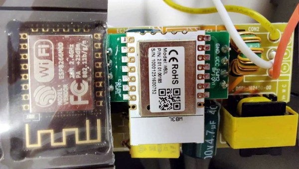
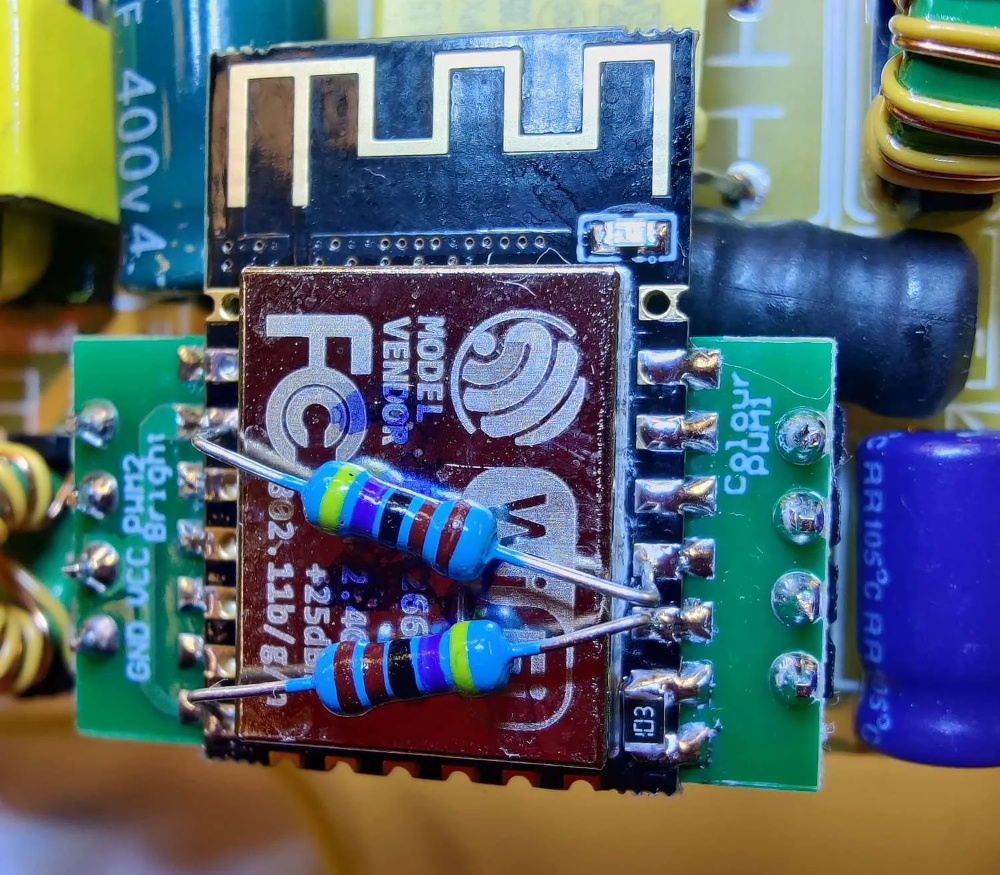
The light in question is a Phillips Hue Ambiance, and [Wejn]’s excellently-documented six part series takes us through the process of creating a replacement light driver. It’s a good read, including reverse-engineering the PWM functions to get the lights to dim exactly like stock, and a dive into the Zigbee protocol so his rebuild light could still talk to the Philips Hue hub. The firmware [Wejn] wrote for the ESP32C6 he chose to use for this project is on GitHub, with the PCB in a second repo.

We want to applaud [Wejn] for his excellent documentation and open-sourcing (the firmware and PCB are under GPL v3). Not only do we get enough information to replicate this project perfectly if we so choose, but by writing out his design process, [Wejn] gives everyone reading a good head start in doing something similar with other hardware. Even if you’re scratching your head wondering why a light switch isn’t good enough anjymore, you have to appreciate what [Wejn] is offering the community.

We’ve covered domestic brain transplants in the past — which is easier in this sort of light than the close confines of a smart bulb. If you’re still wondering why not just use a light switch, perhaps you’d rather hack the light to run doom instead.

Before you go, can we just take a moment to appreciate how bizarre the world has become that we have a DOOM-capable computer to run fancy light fixture? If you’re using what might have been a decent workstation in days of yore to perform a painfully mundane task, let us know on the tips line.

Replacing An ESP8266 Clone With The Real Thing

The first time [konbaasiang] ordered some ceiling LED lights from Tuya, he was pleased to find they contained an ESP-12F that could easily be flashed with a different firmware. So when he ordered 30 more of them at a cost of nearly $900 USD, you can understand his frustration to find that the popular WiFi-enabled microcontroller had been swapped out for a pin-compatible clone that Tuya developed called the WB3L.

Some people would have just chalked this one up to bad luck and used the Tuya-supplied software to control their new lights, but not [konbaasiang]. Since the new chip was outwardly identical to the ESP8266, he decided to take the nuclear option and replace them with the genuine article. With a comfortable spot to work from and a nice microscope, he started on his desoldering journey.

Now it would have been nice if he could have just dropped in a real ESP-12F and called it a day, but naturally, it ended up being a bit more complex than that. The WB3L apparently doesn’t need external pull up and pull down resistors, but [konbaasiang] needed them for the swap to work. He could have come up with some kind of custom adapter PCB, but to keep things simple he decided to run a pair of through hole resistors across the top of the ESP-12F for GPIO 1/2, and use a gingerly placed SMD resistor to hold down GPIO 15.

[konbaasiang] reports that all 30 of the lights survived the transplant and are now running his own  homebrew firmware. While this story had a happy ending, it’s still a cautionary tale. With a growing trend towards replacing the venerable ESP8266 with cheaper and less hacker-friendly silicon, buying IoT hardware with the intent to replace its firmware is likely to get riskier in the near future.

A Smart Way To Wire Smart Switches

Smart switches are fun, letting you control lights and appliances in your home over the web or even by voice if you’re so inclined. However, they can make day-to-day living more frustrating if they’re not set up properly with regards to your existing light switches. Thankfully, with some simple wiring, it’s possible to make everything play nice.

The method is demonstrated here by [MyHomeThings], in which an ESP8266 is used with a relay to create a basic smart switch. However, it’s wired up with a regular light switch in a typical “traveller” multiway switching scheme – just like when you have two traditional light switches controlling the same light at home. To make this work with the ESP8266, though, the microcontroller needs to be able to know the current state of the light. This is done by using a 240V to 3.3V power supply wired up in parallel with the light. When the light is on, the 3.3V supply is on. This supply feeds into a GPIO pin on the ESP8266, letting it know the light’s current state, and allowing it to set its output relay to the correct position as necessary.

This system lets you use smart lighting with traditional switches with less confused flipping, which is a good thing in our book. If you’re using standalone smart bulbs, however, you could consider flashing them with custom firmware to improve functionality. As always, if you’ve got your own neat smart lighting hacks, be sure to let us know!