3D Print A Stenciling Frame For Your PCB

For many a hacker, stenciling a board for the first time is a game-changing experience – the solder joints you get, sure do give your PCB the aura of a mass-manufactured device. Now, you might not get a perfect print – and neither did [Atul R]. Not to worry, because if you have a 3D printer handy, he’s showing you how to design a 3D-printed frame using Blender and TinkerCAD, making your solder paste print well even if you’re trying to rest a giant stencil on top of a tiny board.

[Atul]’s situation was non-characteristic – the project is a 2mm thick PCB designed to plug right into a USB port, so the usual trick of using some scrap PCBs wouldn’t work, and using a 3D-printed frame turned out to be key. To get it done, he exported a .wrl from KiCad, processed it in Blender, and then designed a frame with help of TinkerCAD. These techniques, no doubt, will translate into your CAD of choice – especially if you go with .step export instead of .wrl.

This kind of frame design will get you far, especially for boards where the more common techniques fail – say, if you need to assemble a double-sided board and one side is already populated. Don’t have a stencil? You could surely make a 3D printed stencil, too, both for KiCad boards and for random Gerber files. Oh, and don’t forget this 3D-printable stencil alignment jig, while you’re at it – looks like it ought to save you quite a bit of trouble.

DIY PCB Fixture Helps You Spread The Paste

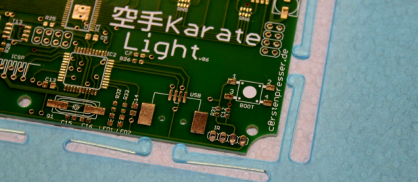
(Yeah, we don’t know what that title means either.) But holding your PCBs down in one place and nicely registered while you spread solder paste over them is a problem that needs solving, and [Carsten] did it nicely.

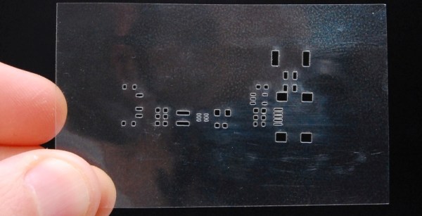
High volume PCB manufacturers have expensive screen printers to do this. The standard hardware hacker solution is to tape some scrap PCBs of the same thickness down to the table to hold the PCBs solidly in place. But if you’re doing a large run, and if you’re already firing up the laser to cut out mylar stencils, you might as well cut out some PCB-holding fixtures to match.

[Carsten]’s blog entry is short on details, but you get the idea just from looking at the picture, right? Adding registration pins to the holder that engage with the stencils could make this a real time-saver as well. As long as you’re lasering the stencil and the holder, there’s nothing stopping you. It’s a simple idea, but a good one, so we thought we’d share. Our only remaining question: what’s a Karate Light?

Laser Etched Stencils

Cutting SMT Stencils With A Laser

Prototyping your own PCBs? At a loss for how to apply your SMT electronics? Well — do you have access to a laser? [Felix] shows us a definitive way to use a laser cutter to engrave SMT stencils with ease.

The real trick here is to engrave — not to cut. Typically if you’re using enough power to cut straight through the plastic, you’re going to get melting and burning of the edges — which won’t work well for a SMT stencil. So what [Felix] found is to engrave at approximately 20-30W @ 400-450mm/s. He’s using Mylar as the material.

The results are pretty awesome — but if you’re without a laser, he also has an excellent tutorial on DIY metal SMT stencils by chemically etching soda can metal!

Continue reading “Cutting SMT Stencils With A Laser”