Hacklet 47 – Thermal Imaging Projects

Thermal imaging is the science of converting the heat signature of objects to an image visible to humans. Everything above absolute 0 gives off some heat, and thermal imagers allow us to see that – even if there is no visible light in the room. Historically, thermal imaging systems have been large and expensive. Early systems required liquid nitrogen cooling for their bolometer sensors. Recent electronic advances have brought the price of a thermal image system from the stratosphere into the sub $300 range – right about where makers and hackers can jump in. That’s exactly what’s happened with the Flir Lepton module and the Seek Thermal camera. This week’s Hacklet is all about thermal imaging projects on Hackaday.io!

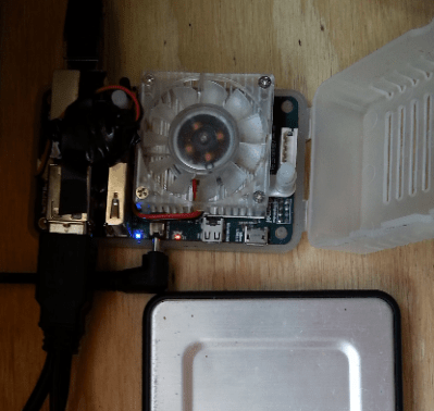
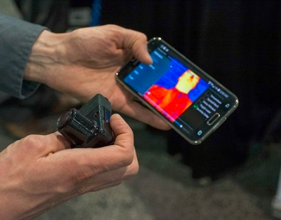
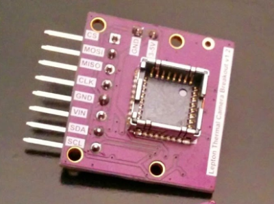
We start with [Pure Engineering] and Flir Lepton Thermal Camera Breakout. Flir’s Lepton thermal camera created quite a stir last year when it debuted in the Flir One thermal iPhone camera. The Lepton module used in the Flir One is a great standalone unit. Interfacing only requires an I2C interface for setup and an SPI interface for image data transfer. Actually using the Lepton is a bit more of a challenge, mainly because of its packaging. [Pure Engineering] made a simple breakout board which makes using the Lepton easy. It’s also breadboard compatible – which is a huge plus in the early phases of any project.


grideye
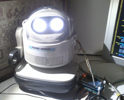
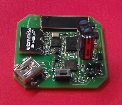
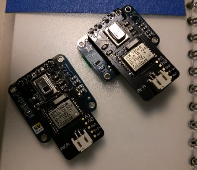
Next up is [AKA] with GRID-EYE BLE-capable thermal camera. This project is a Bluetooth low energy (BLE) thermal camera using Panasonic’s Grid-EYE 64 pixel thermal sensor. 64 pixels may not sound like much, but an 8×8 grid is enough data to see quite a bit of temperature variation. If you don’t believe it, check the project page for a video of [AKA] using Grid-EYE’s on-board OLED display. Grid-EYE was a Hackaday Prize 2014 semifinalist, and we featured a bio on [AKA] last year. The only hard part with building your own Grid-EYE is getting the sensor itself. Panasonic doesn’t sell them to just anyone, so you might have to jump through a few hoops to get your own.


pylepton
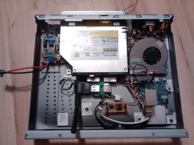
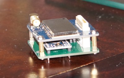
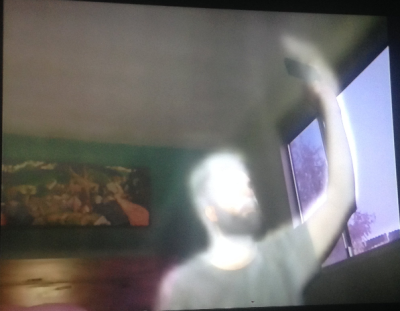
[Kurt Kiefer] brought the FLIR Lepton to the Raspberry Pi with pylepton video overlay. This project uses the Lepton to overlay thermal data with images captured by the Raspbery Pi camera module. The Lepton interfaces through the I2C and SPI ports on the Pi’s GPIO pins. The results are some ghostly images of black and white thermal views over color camera images – perfect for your next ghost hunting expedition!  The entire project is implemented in Python, so it’s easy to import and use pylepton in your own projects. [Kurt] even gives an example of capturing an image with just 5 lines of code. Nice work, [Kurt]!


wificam
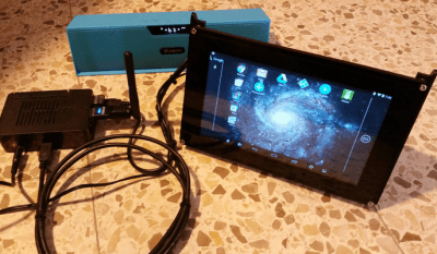
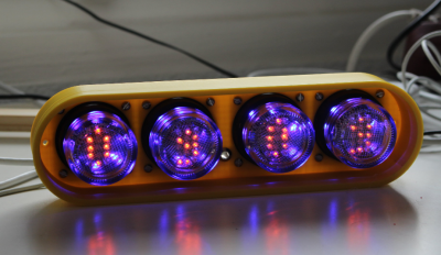
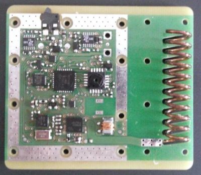
Finally we have [Erik Beall] with WiFi Thermal Camera. [Eric] is using an 82×62 diode array to create thermal images. Unlike microbolometer sensors, diode/thermopile sensors don’t need constant calibration. They also are sturdier than Microelectricomechanical System (MEMS) based devices. This particular project users an array from Heimann Sensor. As the name implies, the sensor is paired with a WiFi radio, which makes using it to capture and display data easy. [Erik] must be doing something right, as WiFi Thermal Camera just finished a very successful Kickstarter, raising $143,126 on a $40,000 initial goal.

Are you inspired? A thermal imager can be used to detect heat loss in buildings, or heat generated by electrical faults – which means it would be a great project for the 2015 Hackaday Prize! If you want to see more thermal imaging projects, check out the thermal imaging projects list!

That’s it for this week’s Hacklet, As always, see you next week. Same hack time, same hack channel, bringing you the best of Hackaday.io!

Hacklet 46 – ODROID Projects

It seems you can’t mention the Raspberry Pi these days without someone bringing up the Odroid. Named after the combination of Open and Android, the current Odroid brand covers several boards – the U3, the UX3 with its 2 Ghz Samsung quad-core processor, and the C1, which is directly aimed at our favorite fruit pie computer. With all this popularity, one would expect a few awesome projects based around the Odroid machines, and you’d be right! This week’s Hacklet is all about projects using the Odroid on Hackaday.io!

Robbie jrWe start with [herrkami] and CRONUS. Cronus started life as a Robbie Junior, Radio Shack’s re-branded version of Takara Tomy’s Omnibot Jr.  [herrkami] has upgraded Cronus’ brain with an Odroid U3. Cronus can now reliably respond to voice commands thanks to a little help from Google’s speech recognition engine and the accompanying Python API. Cronus is rather conversational as well, all due to the AIML framework. [herrkami] hopes to cut the cord (or WiFi link) once he gets CMU sphinx up and running. Some of [herrkami’s] best work is in his cardboard templates to create a mechanism for turning Cronus’ head. These are some pretty sweet updates for a 1986 vintage robot!


serverNext up is [tlankford01] with Linux Tutorial: Odroid U3 Server w/ Seafile Cloud. [tlankford01] walks us through setting up a file server using the Odroid, a 16 Gigabyte EMMC card, and a hard drive to hold the files. As one might expect, this tutorial covers a LAMP (Linux, Apache, MySQL, PHP) server stack. The 9 project logs take us from a bare microSD card to a full server. The Odroid’s 2 Gigabytes of ram are put to good use running the open source Seafile cloud server package. Tutorials like this deserve lots of love from the Hackaday.io community. Sometimes you just need to get a solid file server up and running. When that happens, this type of project is often just what the doctor ordered! So don’t be a lurker, head over to [tlankford01]’s page and give him a skull!


touch[Victor] gets us one step closer to an Odroid tablet with the HDMI touchscreen. HDMI touchscreen is a project to connect a 7″ 1024 x 600 LCD with a capacitive touchscreen to HDMI based computers. The heart of the project is Texas Instrument’s TFP401 panelbus DVI receiver chip. This chip makes interfacing LCD screens to HDMI or DVI video cards (almost) painless. There still is a bit of X configuration to do to get things running. [Victor] even got his Odroid running in Android with his custom screen setup. Those of us who have spent time in display an input configuration file limbo know that this is no small feat!

htpcFinally we have [darth_llamah] with Odroid-U3 HTPC. [Darth] raided his junkbox and parts drawers to build a solid home theater PC using the Odroid-U2. The U2 is a bit older than the current U3 models, but all [Darth’s] work should apply to any of the Odroid series. An old Itona case provided the frame for this hack, but it took a lot of custom work with plastic and epoxy to make everything fit. [Darth’s] software stack is the popular OpenELEC Linux build. [Darth] even setup a real “soft” power button using an ATtiny85 connected to USB and s Adafruit’s TrinketHidCombo library.

If you want to see all the Odroid projects in one place, check out our new Odroid projects list!

That’s it for this Hacklet, As always, see you next week. Same hack time, same hack channel, bringing you the best of Hackaday.io!

Hacklet 45 – Reverse Engineering Projects

Sooner or later, all of us end up putting on our reverse engineering hats and digging in to a device. It might be that you’re trying to keep an old piece of equipment running – the manufacturer is long defunct, and parts are no longer available. It might be that sweet new router with locked down firmware. Or, it might just be that you’re curious. Whatever the reason, reverse engineering is a rewarding endeavor. Some of our favorite reverse engineering projects read like spy novels. Instead of cloak and dagger, it’s encryption and soldering iron. This week’s Hacklet focuses on some of the best reverse engineering projects on Hackday.io!

c02We start with [Henryk Plötz] and Reverse-Engineering a low-cost USB CO₂ monitor. Carbon monoxide detection and measurement devices are household safety items these days, and have become rather cheap. Carbon dioxide measuring devices are less common, and as expected, more expensive. [Henryk] found a device for around 80€ which did what he needed. The included USB connector was supposedly just for power, but when plugging it in, the device enumerated on his Linux box. The accompanying windows software displayed live data from the detector, but there wasn’t much information on the protocol. Time to bust out Ida pro, and go to town on that software! [Henryk] did battle with his CO₂ monitor”s software and was justly rewarded.

mavrickNext up is [Bob Blake] and Reverse Engineering the Maverick ET-732. [Bob] loves barbecue, but hates to babysit his smoker. Thankfully there are wireless temperature sensors out there built just for that purpose, but they have limited range and you can’t have multiple receivers around the house. [Bob] aimed to fix all of that by sending his Maverick wireless thermometer data to the web, so he could check in on his cooking from anywhere. First he had to reverse engineer the protocol used by the sensor. A spectrum analyzer told [Bob] that the sensor transmit frequency was  433.92 MHz, which is common for low-cost transmitters like this. [Bob] actually had some compatible receivers at his office, so he was quickly able to capture some data with his Saleae logic analyzer. The real fun came in figuring out exactly how the data was organized!

hmdA chance Ebay sale netted [Technics] a sweet head mounted magnifier, but no way to control it. Reverse engineering a Life Optics M5 documents [Technics] efforts to get his new headgear working. The Life Optics M5 is actually a re-branded version of the Leica HM500 head mounted zoom microscope. These devices were originally designed for medical use. They provide a stereo view to the surgeon or dentist using them, as well as sending a video feed to be displayed for the rest of the team to use or record. Cracking open the M5’s head-mounted box revealed several modules, but no obvious means of controlling zoom or focus. Scoping out a few of the mystery wires did reveal what looks to be a 9600 baud serial data stream though. This is a brand new project, and we’re waiting for [Technics] next update to see if he gets to do some soldering with his new toy!


biosBIOS password protection – it’s the bane of any used laptop buyer’s existence. Sometimes removing these passwords are as easy as popping out the CMOS battery, other times, not so much. [q3k] found themselves in the latter situation with a bundle of Toshiba R100 laptops. and no way to start them up. [q3k] didn’t give up though – they broke out the soldering iron and started Reverse engineering Toshiba R100 BIOS. The R100 is a Pentium M era machine – old but still usable for many hacking purposes. Dumping the ROM BIOS of the laptop didn’t yield the information [q3k] needed, so they moved on to the TLCS-870 controller, and built a really nice board with a Xilinx Spartan6 FPGA to help with the effort. It turns out that the 870 is just used for power management. – [q3k] has now turned their attention to a Renesas microcontroller which might be just the droid they are looking for!

We think that reverse engineering projects are pretty darn cool, so we’ve created a Reverse Engineering List to keep them all organized.

That’s it for this Hacklet, As always, see you next week. Same hack time, same hack channel, bringing you the best of Hackaday.io!

Hacklet 44 – Teardowns

Just about every hacker, maker and tinkerer out there received their early education the same way: A screwdriver in one and a discarded bit of electronics in the other. There is no better way to find out how something works than cracking it open and examining each piece.  In recent years, teardown videos have become popular on YouTube, with some of the great examples coming from users like [EEVblog], [mikeselectricstuff], and [The Geek Group]. This week’s Hacklet is all about the best teardown projects on Hackaday.io!

copierWe start with [zakqwy] and his Savin C2020 Teardown. Photocopiers (and multifunction machines) are the workhorses of the modern office. This means there are plenty of used, abused, and outdated photocopiers available to hackers. [Zakqwy] got this monster when it started misbehaving at his office. Copiers are a venerable cornucopia of motors, gears, sensors (lots and lots of breakbeam sensors) and optics. The downside is toner: it’s messy, really bad to breathe, and if you don’t wear gloves it gets down into the pores of your skin, which takes forever to get out. [Zakqwy] persevered and found some awesome parts in his copier – like an  Archimedes’ screw used to transport black toner.

wemoNext up is [Bob Blake] with Belkin WeMo Insight Teardown. [Bob] wanted a WiFi outlet, but wasn’t about to plug something in to both his power grid and his network without taking it apart first. [Bob] did an awesome job of documenting his teardown with lots of great high resolution photos – we love this stuff! He found a rather well thought out hardware design. The Insight has 3 interconnected PCBs inside. The power switching and supply circuits are all on one board. It includes slots and the proper creep distances one would expect in a design that will be carrying 120V AC mains power. A small daughter board holds an unknown chip – [Bob] is guessing it is the power sensing circuitry. A third board a tucked in at the top of the module holds the main CPU, a Ralink/MediaTek RT5350F SoC, RAM, and the all important WiFi antenna.


x-ray[Drhatch] took things into the danger zone with an X-ray Head Teardown. We’re not sure if [Drhatch] is a real doctor, but he does have a Heliodent MD dental X-ray head. Modern X-ray machines are generally radiation safe if they’re not powered up. Radiation isn’t the only dangers to worry about though – there are latent charged capacitors and cooling oils which may contain nasty chemicals like PCBs, among other things. [Drhatch] found some pretty interesting design decisions in his X-ray head. The tube actually fires through the cylindrical high voltage transformer. This means the transformer acts as a beam collimator, focusing the X-ray beam down like a lens. He also found plenty of lead shielding. Interestingly there are two thickness of lead in the housing. Shielding close to the tube is 1 mm thick, while shielding a bit further away is only 0.7 mm thick.


3phaseFinally, we have [danielmiester] with Inside a 3ph AC Motor Controller(VFD). [Daniel] tore down a Hitachi Variable-Frequency Drive (VFD) with the hopes of creating a frequency converter for a project. These high voltage, high power devices have quite a bit going on inside, so the conversion became a teardown project all its own. VFDs such as this one are used in industry to drive high power AC motors at varying speeds efficiently. As [Daniel] says, the cheaper ones are ” just really fancy PWM modules”. Handling 1.5 kW is no joke though. This VFD had a large brick of power transistors potted into its heat sink. The controller board was directly soldered to the transistors, as well as the rectifier diodes for the DC power supply. [Daniel] was doing some testing with the unit powered up, so he built a custom capacitor discharge unit from 3 C7 Christmas lights. Not only did they keep the capacitors discharged, they provided an indication that the unit was safe. No light means no charge.

Not satisfied? Want more teardown goodness? Check out our freshly minted Teardown List!

That’s about all the time we have for this week’s Hacklet. As always, see you next week. Same hack time, same hack channel, bringing you the best of Hackaday.io!

Hacklet 43 – Flashlight Projects

Mankind has always looked for ways to light up the night as they walk around. Fires are great for this, but they aren’t very safe or portable. Even kept safe in a lantern, an open flame is still dangerous – especially around cows.  Enter the flashlight, or torch if you’re from the other side of the pond. Since its invention in 1899, the flashlight has become a vital tool in modern society. From patrolling the dark corners of the city, to reading a book under the covers, flashlights enable us to beat back the night. The last decade or so has seen the everyday flashlight change from incandescent bulbs to LEDs as a light source. Hackers and makers were some of the first people to try out LED flashlights, and they’re still tinkering and improving them today. This weeks Hacklet focuses on some of the best flashlight projects on Hackaday.io!

light1We start with [Norman], and the LED Flashlight V2. Norman built a flashlight around a 100 Watt LED. These LEDs used to be quite expensive, but thanks to mass production, they’ve gotten down to around $6 USD or so. Norman mounted his LED a custom aluminum case. At this power level, even LEDs get hot. An extruded aluminum heatsink and fan keeps things cool. Power is from a 6 cell LiPo battery, which powers the LED through a boost converter. It goes without saying that this flashing is incredibly bright. Even if the low-cost LEDs aren’t quite 100 Watts, they still put many automotive headlights to shame! Nice work, [Norman].

light2A tip of the fedora to [Terrence Kayne] and his Grain-Of-Light LED LIGHT. [Terrence] loves LED flashlights, be he wanted one that had a bit of old school elegance. Anyone familiar with LEDs knows CREE is one of the biggest names in the industry. [Terrence] used a CREE XM-L2 emitter for his flashlight. He coupled the LED to a reflector package from Carlco Optics. The power source is an 18650 Lithium cell, which powers a multi-mode LED driver. [Terrence] spent much of his time turning down the wooden shell and aluminum tube frame of the flashlight. His workmanship shows! Our only suggestion would be to go with a lower profile switch. The toggle [Terrence] used would have us constantly checking our pockets to make sure the flashlight hadn’t accidentally been activated.

light3Harbor Freight’s flashlights are a lot like their multimeters: They generally work, but you wouldn’t want to trust your life to them. That wasn’t a problem for [Steel_9] since he needed a strobe/party light. [Steel_9] hacked a $5 “27 LED” light into a stylish strobe light. He started by cutting the power traces running to the LED array. He then added in an adjustable oscillator circuit: two BJTs and a handful of discrete components make up an astable multivibrator. A third transistor switches the LEDs. Switching a load like this with a 2N3906 probably isn’t the most efficient way to do things, but it works, and the magic smoke is still safely inside the semiconductors.  [Steel_9] built the circuit dead bug style, and was able to fit everything inside the original plastic case.  Rave on, [Steel_9]!

If you want to see more flashlight projects, check out our new list on Hackaday.io! That’s about all the time we have for this week’s Hacklet. As always, see you next week. Same hack time, same hack channel, bringing you the best of Hackaday.io!

Hacklet 37 – Nixie Projects

Nothing quite beats the warm glow of a tube. What better way to enjoy that glow than to use it to read numbers? Nixie tubes were created by Haydu Brothers Laboratories, and popularized by Burroughs Corp in 1955. The name comes from NIX I – or “Numeric Indicator eXperimental No. 1”. By the mid 1970’s, seven segment LED’s were becoming popular and low-cost alternatives to Nixies, but they didn’t have the same appeal. Nixie tubes were manufactured all the way into the 1990’s. There’s just something about that tube glow that hackers, makers, and humans in general love. This week’s Hacklet highlights the best Nixie (and Nixie inspired) projects on Hackaday.io!

temperatureDisplayWe start with [Sascha Grant] and Nixie Temperature Display. [Sascha] mixed an Arduino, a Dallas DS18B20 Temperature sensor, and three IN-12A Nixie tubes to create a simple three digit temperature display. We really love the understated laser-cut black acrylic case. An Arduino Pro Micro reads the Dallas 1-wire sensor and converts the temperature to BCD. High voltage duties are handled by a modular HV power supply which bumps 9V up to the required 170V.  Controlling the Nixie tubes themselves are the classic K155ID1 BCD to decimal converter chips – a favorite for clock builders.


driverNext up is [Christoph] with Reading Datasheets and Driving Nixie Tubes. Chips like the K155ID1, and the 74141 make driving Nixie tubes easy. They convert Binary Coded Decimal (BCD) to discrete outputs to drive the cathodes of the Nixie. More importantly, the output drivers of this chip are designed to handle the high voltages involved in driving Nixie tubes. These chips aren’t manufactured anymore though, and are becoming rare. [Christoph] used more common parts. His final drive transistor is a MPSA42 high voltage NPN unit. Driving the MPSA42’s is a 74HC595 style shift register. [Christoph] used a somewhat exotic Texas Instruments TPIC6B595 with FET outputs, but any shift register should work here. The project runs on a Stellaris Launchpad, so it should be Arduino compatible code.

fixietube[Davedarko] has the fixietube clock. Fixietube isn’t exactly a Nixie. It’s an LED based display inspired by Nixie tubes. Modern amber LEDs aren’t quite the same as classic Nixies, but they get pretty darn close. [Dave] designed a PCB with a 3×5 matrix of LEDs to display digits. A few blue LEDs add a bit of ambient light. The LEDs are driven with a 74HC595 shift register. The entire assembly mounts inside a tiny glass jam jar, giving it the effect of being a vacuum tube. The results speak for themselves – fixietubes certainly aren’t Nixies, but they look pretty darn good. Add a nice 3D printed case, and you’ve got a great project which is safe for anyone to build.

openNixieFinally, we have [Johnny.drazzi] with his Open Nixie Clock Display. [Johnny] has been working on Open Nixie for a few years. The goal is to create a Nixie based clock display which can be driven over the SPI bus. So far, [Johnny] has 6 Russian IN-12 tubes glowing with the help of the ubiquitous K155ID1 BCD to decimal converter. The colons of the clock are created with two INS-1 neon indicators. [Johnny] spends a lot of time analyzing the characteristics of a Nixie tube – including the strike voltage, and steady state current. If you’re interested in building a Nixie circuit yourself, his research is well worth a read!

Not satisfied? Want more Nixie goodness? Check out our Nixie tube project list!

That’s about all the time we have for this week’s Hacklet. As always, see you next week. Same hack time, same hack channel, bringing you the best of Hackaday.io!

Hacklet 34 – Satellite Projects

Space. The final frontier. Every tinkerer, hacker, and maker has dreamed of flying out of Earth’s atmosphere and into the heavens. Last year one hard-working team got a chance to fly a member to space by winning the Hackaday prize. For the rest of us, we can still experience some of that excitement by contacting satellites in orbit, or even sending a bit of our own hardware into space. This week’s Hacklet focuses on the best satellite projects on Hackaday.io!

basicSatWe start with [movax] and Your satellite devkit and launch. Chipsat is a tiny satellite which runs BASIC code. Yes, BASIC in space! Chipsats will be stacked into a launcher and sent off into space in groups. The idea is to eventually have them launched from the International Space Station. Power is provided by a small solar cell which charges up a pair of super capacitors. When the capacitors are charged, the satellite will run for a few seconds. Connectivity with the ground is via a 433 MHz link. Chipsat doesn’t just float in space, three coils give it the ability to control its attitude and rotation. Chipsat will sense the space around it with a magnetometer and a light sensor.


satnogsv2

No satellite-themed Hacklet would be complete without [Pierros Papadeas] and his team’s work on SatNOGS – Global Network of Ground Stations. SatNOGS aims to create a global network of connected satellite ground stations. Think of it as a grass-roots version of NASA’s deep space network for satellites in earth orbit. This is more than just a great idea, as SatNOGS won the 2014 Hackaday Prize. You can check out our coverage of the project back in November, 2014. Since then, the SatNOGS team has been busy! They’ve just deployed the first SatNOGS V2 system above their hackerspace in Athens, Greece.

trsiNext up is TRSI PocketQub Satellite, another project by [movax]. TRSI is a satellite that sends data via images which can be viewed with a simple RTL-SDR stick using Hellschreiber mode. Hell mode means that images can be directly viewed in the waterfall display of whichever SDR application is running the receiver. Numbers or entire images snapped with TRSI’s cell phone style camera module can be encoded and displayed. Power is of course provided by solar cells, and the communications link will be on the coordinated 433 MHz band. The original TRSI hardware has actually morphed into a deployment machine for ChipSat, [morvax’s] other satellite project. He’s put the main TRSI program on hold until after the ChipSat campaign is complete.

pocketquRounding out our satellite special is [OzQube] with his project QubeCast Max. QubeCast is the first Australian version of the PocketQube PQ60 satellite form factor. After watching the success of $50Sat project, [OzQube] wanted to design a satellite of his own. Since he wanted to add sensors and send more data back to Earth than previous efforts, he needed a higher data rate than the current crop of satellites. This meant going to a high-powered radio. To achieve this, he’s using a  NiceRF RF4463F30 radio module. The module is based upon a Silicon Labs Si4463 RF ISM band chip, coupled with a power amplifier. The module outputs 1 watt, which is quite a bit of power for a tiny satellite!

Want more satellite goodness? Check out Hackaday.io’s freshly minted Satellite List.

The countdown is almost at 0, so that’s just about all the time we have for this episode of the Hacklet. See you next week.  Same hack time, same hack channel, bringing you the best of Hackaday.io!