On the surface, a programmable logic controller (PLC) might seem like nothing more than a generic microcontroller, perhaps outfitted to operate in industrial settings with things like high temperatures or harsh vibrations. While this is true to some extent, PLCs also have an international standard for their architecture and programming languages. This standard is maintained by the International Electrotechnical Commission, making it so that any device built under these specifications will be recognizable to control engineers and maintenance personnel worldwide. And, if you use this standard when working with certain Arduinos, this common platform can become a standard-compliant PLC as well.
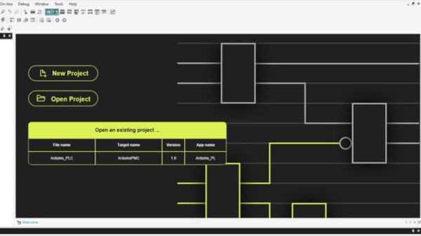
The IDE itself supports programming ladder diagrams, functional block diagrams, and other programming systems covered under the IEC 61131-3 standard. Not only that, it allows the combination of these types of PLC programming with Arduino sketches. The system offers many of the perks of PLC programming alongside the familiar Arduino platform, and supports a number of protocols as well including CANOpen, Modbus RTU, and Modbus TCP. It can also be used for monitoring a PLC system, essentially adding IoT capabilities to existing systems, enabling continuous monitoring, debugging, and program updates.
While not every Arduino is a great platform to build a PLC around, there are a few available for those looking for a system a little less proprietary and a little more user-friendly than typical PLC systems tend to be. There’s a reason that PLCs are built around an international standard and generally have certain hardware in mind to run it, though, and this comparison of a Raspberry Pi with an off-the-shelf PLC goes into detail about why certain components aren’t good choices for PLCs.
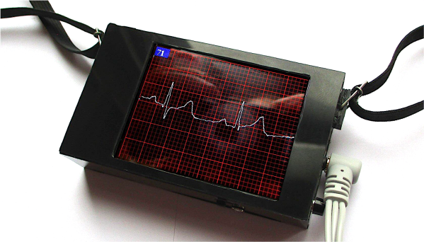
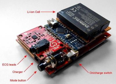
If you’ve followed Hackaday for any period of time, you’re probably already somewhat familiar with the hardware needed to record the ECG. First, you need a high input impedance instrumentation amplifier to pick up the millivolt signal from electrical leads carefully placed on the willing subject’s body. To accomplish this, he used an AD8232 single-lead ECG module (we’ve actually seen this part used to make a soundcard-based ECG). This chip has a built-in instrumentation amplifier as well as an optional secondary amplifier for additional gain and low-pass filtering. The ECG signal is riddled with noise from mains that can be partially attenuated with a simple low-pass filter. Then, [Peter] uses an Arduino Nano to sample the output of the AD8232, implement a digital notch filter for added mains noise reduction, and display the output on a 2.8″ TFT display.
Other than the circuit itself, two things about his project really caught our attention. [Peter] walks the reader through all the different safety considerations for a commercial ECG device and applies these principles to his simple DIY setup to ensure his own safety. As [Peter] put it, professional medical electronics should follow IEC 60601. It’s a pretty bulky document, but the main tenets quoted from [Peter’s] write-up are:
limiting how much current can pass through the patient
how much current can I pass through the patient?
what electrical isolation is required?
what happens if a “component” fails?
how much electromagnetic interference can I produce?
what about a defibrillator?
[Peter] mentions that his circuit itself does not fully conform to the standard (though he makes some honest attempts), but lays out a crude plan for doing so. These include using high-valued input resistors for the connections to the electrodes and also adding a few protection diodes to the electrode inputs so that the device can withstand a defibrillator. And of course, two simple strategies you always want to follow are using battery power and placing the device in a properly shielded enclosure.
[Peter] also does a great job breaking down the electrophysiology of the heart and relates it to terms maybe a bit more familiar to non-medical professionals. Understanding the human heart might be a little less intimidating if we relate the heart to a simple voltage source like a battery or maybe even a function generator. You can imagine the ions in our cells as charger carriers that generate electrical potential energy and nerve fibers as electrical wires along which electrical pulses travel through the body.
Honestly, [Peter] has a wealth of information and tools presented in his project that are sure to help you in your next build. You might also find his ECG simulator code really handy and his low-memory display driver code helpful as well. Cool project, [Peter]!
In an earlier article, I covered Fire Hazard Tests that form an important part of safety testing for electronic/electrical products. We looked at the standards and equipment used for abnormal heat, glowing wire and flame tests. A typical compliance test report for an appliance, such as a toaster, will be a fairly long document reporting the results for a large number of tests. Among these, the section for “Heat and Fire” will usually have the results of a third test – Tracking. It’s a phenomena most of us have observed, but needs some explanation to understand what it means.
What is Tracking ?
Tracking is a surface phenomena on an insulating material. When you have two conducting terminals or tracks at a high voltage (higher than 100 VAC) separated by an insulator, a combination of environmental factors such as dust, moisture and thermal cycling could cause minute leakage currents to flow on the surface between the conductors. Over time, the deposits carbonize and the surface current increases. Eventually, a carbon track forms over the surface of the insulator making it conductive at a particular “tracking” voltage. Finally, a short circuit is created between the two conductors which may also lead to fire. Worse, it’s possible that the tracking current could be lower than the rating of the protective fuse in the appliance, which will prevent the electrical supply from being cut off, creating a fire hazard. Tracking can be avoided by using the right kind of insulating materials and adequate creepage and clearance distances. One of the reasons for adding a slot between adjacent high voltage terminations or tracks on a PCB is to take care of tracking.
Test Standards
It’s impossible to conduct such tests according to real world conditions, so a standardized procedure is needed which can produce results that allow different materials to be compared. The IEC’s Technical sub-committee 15E was previously entrusted with the work of creating and maintaining tracking index methods and standards. Considering the importance of this standard and its wide implications, this work is now handled by TC 112 — Evaluation and qualification of electrical insulating materials and systems.
TC 112’s document IEC 60112 defines a “standardized method for the determination of the proof and the comparative tracking indices of solid insulating materials” for voltages up to 600 VAC, and provides information on how to design a suitable test equipment. The ASTM has an equivalent document — ASTM D3638 as does the UL — UL 746A-24. A more severe test is covered under IEC 60587 — “Electrical insulating materials used under severe ambient conditions – Test methods for evaluating resistance to tracking and erosion”. This test is often referred as the inclined plane tracking and erosion test and specifies test voltages up to 6 kV. But for now, let’s just look at the low voltage test as per IEC 60112.
Procedure
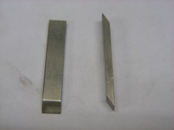
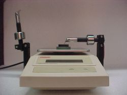
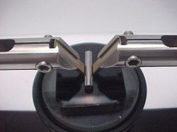
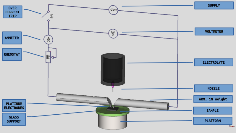
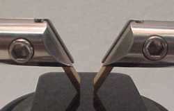
A sample of at least 20 mm x 20 mm with a minimum thickness of 3 mm is required for testing, with a set of five samples being tested each time. If the test product cannot provide a sample of these dimensions, then tiles of the insulating material need to be specifically produced using the same moulding process as used in actual production. The sample is supported on a horizontal glass platform. Two chisel-edged platinum electrodes are placed over the sample, separated by a gap of 4 mm. A voltage adjustable between 100 to 600 VAC is applied to these electrodes. The electrodes weigh down on the sample with a force of 1 N via dead weights.
The electrical supply to the electrodes needs to be current limited. For all voltages between 100 V to 600 V, the short circuit current across the electrodes must be limited to 1 A. This is usually done by means of a series variable resistor (rheostat). In some equipment designs, the Variac (variable auto-transformer) for adjusting the voltage is mechanically coupled to the rheostat ensuring the short circuit current is always limited to 1 A. An additional, smaller value rheostat is used for minor trimming. The standard further specifies that after setting the open circuit voltage, the measured voltage at 1 A current should not drop by more than 10% (load regulation). This makes transformer design a bit tricky. At low voltages, there isn’t enough magnetic coupling between the windings, causing higher drops at lower voltages. One solution is to use two secondary windings of about 350 V each which are connected in parallel for test voltage below 300 V, and in series for higher voltages. But there are other ways of satisfying this requirement too. It’s just one example of how the designer needs to look at every requirement in the standard and then figure out how to implement it in the test equipment.
The short-circuit current is just a limiting requirement of the electrical source connected to the electrodes. The more critical setting is the “tripping” current which needs to be set to 0.5 A above which the source must be disconnected from the electrodes. The tripping sensor needs to have a time delay of two seconds before it trips and the reason for this setting will become clear a bit later.
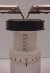
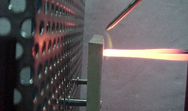
Environmental contamination is simulated by a salt solution — usually ammonium chloride having a concentration of 0.1%. An alternate solution is prescribed for more stringent testing. While applying the test voltage across the electrodes, one drop of the electrolyte is dropped over the test sample between the electrodes every 30 seconds for a total of 50 drops. The size of each drop needs to be adjusted such that 50 drops weigh roughly 1.075 grams and 20 drops weigh 0.430 grams. This can be achieved by careful selection of the needle diameter used for the drops as well as the delivery mechanism. Some designs use a gravity feed, solenoid operated device while others use a peristaltic pump. Another way is to use an air pump which forces the liquid out of its container by forcing air in to it. The test sample passes if it survives 50 drops without triggering the over current sensor. The sample fails if the over-current sensor gets triggered or if it catches fire, at which point the electrical supply needs to be disconnected immediately.
When a drop falls over the sample across the electrodes, most of the electrical current flows through the liquid since it is conductive. This causes a current spike that quickly boils off most of the salt solution, and generally lasts for a second or two. During this two-second duration, the over-current device is programmed not to trip. With most of the water having evaporated, some of the salt is left behind as a deposit over the sample, which causes “tracking” current to flow over its surface. A while later, you will also notice some scintillation effect (sparking) as the leftover salt crystals burn out when the current flows through them.
The results of a tracking test are reported in two different ways. A Proof Tracking Index test (PTI) is usually carried out at 175 V to confirm that the sample can survive 50 drops. On the other hand, a Comparative Tracking Index test is performed over a range of voltages, incrementing the test voltage by 25 V for each succeeding test. The number of drops is always set at 50. The CTI value is determined as the highest voltage at which the sample withstands 50 drops. In some cases, the sample must also pass the test at 25 V less than the CTI voltage for a duration of 100 drops. Depending on the CTI value, the insulator is assigned a Performance Level Category with PLC0 being the highest and PLC5 being the lowest.
It’s always fascinating looking at a sample undergoing the Tracking Index Test — check out the video below. When you look at data sheets for plastic materials, the Tracking Index value will always be reported under it’s electrical properties. Paper Phenolic, which was the PCB substrate used before the advent of fibreglass, usually has a very low tracking index value (depending on its composition), ranging between 100 V to 175 V. On the other hand, depending on composition and filler materials, fibreglass substrates such as FR4 can have CTI values ranging from 175 V up to about 300 V or higher.
If you have ever seen a PCB (not the components on it), give off Magic Smoke, then you’ve seen the effects of Tracking in action. With good design, taking into consideration proper creepage and clearance distances, it is one of the failure modes which can be prevented.
How do you know that new appliance you bought won’t burn your house down? Take a look at any electrical appliance, and you’ll find it marked with at least one, and most often, several safety certification marks such as UL, DIN, VDE, CSA or BSI. Practically every electrical product that plugs into utility supply needs to go through a mandatory certification process to ensure it meets these conformity test requirements. Some examples include domestic and industrial electrical appliances, tools, electrical accessories, consumer electronics and medical electronics.
When you look through a typical safety test standard, you’ll notice it breaks down the various tests in two categories. “Type” tests are conducted on prototypes and samples of the final product or its individual parts and components, and are not generally repeated unless there are changes in design or materials. “Acceptance” tests are routine verification tests conducted on 100% of the products produced. For example, a typical Type test would be used to check the fire retardant properties of the plastics used in the manufacture of the product during development, while a Routine test would be carried out to check for high voltage breakdown or leakage and touch currents on the production line.
Nowadays, a majority of countries around the world adopt standards created by international organizations such as IEC, ISO, and ITU, then fine tune them to suit local requirements. The IEC works by distributing its work across almost 170 Technical Committees and Subcommittees which are entrusted with the job of creating and maintaining standards. One of these committees is “TC89 Fire hazard testing” whose job is to provide “Guidance and test methods for assessing fire hazards of electro-technical equipment, their parts (including components) and electrical insulating materials”. These tests are why we feel safe enough to plug something in and still sleep at night.
Practically all electrical products need to confirm to this set of tests as part of their “Type” test routine. This committee produces fire hazard testing documents in the IEC 60695 series of standards. These documents range from general guidelines on several fire hazard topics to specific instructions on how to build the test equipment needed to perform the tests. It’s interesting to see how some of these tests are carried out and the equipment used. Join me after the break as we take a look at that process.
The International Electrotechnical Commission (IEC) is an international body that issues standards on a wide range of electronics-related topics. How wide? Their mandate seems to span rules for household product safety to the specification of safety logic assemblies in nuclear power plants. Want to know how to electrically measure sound loudness? Test methods for digital door lock systems? Or maybe you’re interested in safety interlock systems for laser processing machines. There’s an IEC standard for that too.
Unfortunately, this information is kept behind a paywall. OK, it’s a lot more like a pay fortress. They really, really don’t want you accessing their documents without first coughing up. This is a shame.
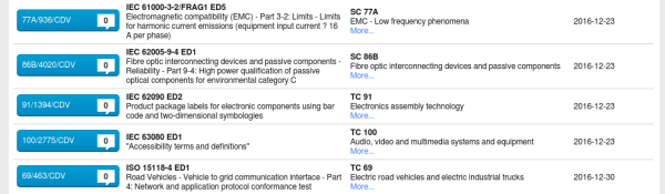
The IEC doesn’t just make the standards in a vacuum, however. Before the scribes touch their chisels to the stone tablets, there are draft versions of the standards that are open for public comment by those knowledgeable in the field. And by “those knowledgeable”, we mean you, dear hacker. Head on over to the public commenting page, sign up, and you’ve got free access to every document that’s currently up for discussion.
Now, it does look like the IEC doesn’t want you sharing these PDFs around — they watermark them with your username and threaten all sorts of things if you use them for anything other than commenting purposes — so don’t go abusing the system. But on the other hand, if you are a private individual who knows a thing or two about a thing or two, we think you’re entirely right to look over their shoulders. Let us know in the comments if you find any gems.
They’ve even got a weekly update feature (in the registration pages) that’ll keep you up to date. And who knows, maybe your two cents, submitted to your country’s chapter of the IEC, will influence future international standards.
After months of cross-disciplinary meetings, some of the largest professional associations just announced their plans to submit an entire standard set for engineers with egos too fragile to accept design criticism. The Special Snowflake Standard or S2 (in compliance with Godwin’s law) ensures compromised mechanical and electrical integrity by ignoring proper design methodologies for more fluid definitions of success. The Special Snowflake Standard allows the modern engineer greater flexibility in avoiding self-improvement in their field while maintaining an advanced level of apparent competency.
The Standard follows an ingenious randomly generated naming scheme to hinder cross-checking and look-up. The honesty being the only change from the current system. It took us a while to navigate the websites built to serve the standards, as they themselves were built to the W3C.S2.01.d.f4r.7 Special Snowflake Standard For Geriatric Exclusion From The Study of Modern Web Development and therefore were only accessible through the Gopher protocol running specifically on SPARC workstations.
Nonetheless, after working through multiple W3C.S2.u.r.f4.u17 Probably PEBKAC Self Exclusion Of Responsibility Standard errors, we found a few standards we’re really excited about. Let’s take a look at a the highlights:

 The electrical supply to the electrodes needs to be current limited. For all voltages between 100 V to 600 V, the short circuit current across the electrodes must be limited to 1 A. This is usually done by means of a series variable resistor (rheostat). In some equipment designs, the Variac (variable auto-transformer) for adjusting the voltage is mechanically coupled to the rheostat ensuring the short circuit current is always limited to 1 A. An additional, smaller value rheostat is used for minor trimming. The standard further specifies that after setting the open circuit voltage, the measured voltage at 1 A current should not drop by more than 10% (load regulation). This makes transformer design a bit tricky. At low voltages, there isn’t enough magnetic coupling between the windings, causing higher drops at lower voltages. One solution is to use two secondary windings of about 350 V each which are connected in parallel for test voltage below 300 V, and in series for higher voltages. But there are other ways of satisfying this requirement too. It’s just one example of how the designer needs to look at every requirement in the standard and then figure out how to implement it in the test equipment.
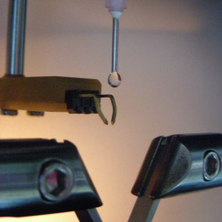 The short-circuit current is just a limiting requirement of the electrical source connected to the electrodes. The more critical setting is the “tripping” current which needs to be set to 0.5 A above which the source must be disconnected from the electrodes. The tripping sensor needs to have a time delay of two seconds before it trips and the reason for this setting will become clear a bit later.
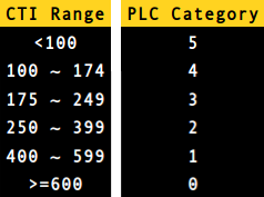 The results of a tracking test are reported in two different ways. A Proof Tracking Index test (PTI) is usually carried out at 175 V to confirm that the sample can survive 50 drops. On the other hand, a Comparative Tracking Index test is performed over a range of voltages, incrementing the test voltage by 25 V for each succeeding test. The number of drops is always set at 50. The CTI value is determined as the highest voltage at which the sample withstands 50 drops. In some cases, the sample must also pass the test at 25 V less than the CTI voltage for a duration of 100 drops. Depending on the CTI value, the insulator is assigned a Performance Level Category with PLC0 being the highest and PLC5 being the lowest.