A Guide To Milling PCBs At Home

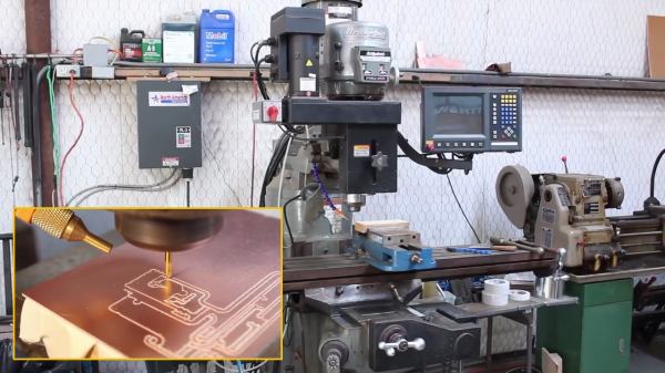
If you keep up with various retro vacuum tube projects, you probably have run across [UsagiElectric] aka [David]’s various PCBs that he makes on his own Bridgeport EZ-Track 3-axis milling machine — massively oversized for the job, as he puts it. In a recent video, [David] walks us through the steps of making a sample PCB, introducing the various tools and procedures of his workflow. He points out that these are the tools he uses, but the overall process should be similar no matter what tools you use.

  • Logisim to validate logic designs
  • TINA-TI, Texas Instrument’s version of the TINA SPICE simulator
  • DesignSpark PCB for schematic entry and PCB layout
  • FlatCAM, a computer-aided PCB manufacturing tool

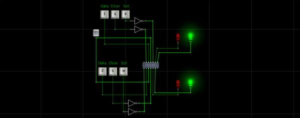
For this video, [David] makes a half-adder circuit out of four vacuum tubes plus a seven-segment VFD tube to show the combined sum and carry outputs. Momentary switches are used to generate the two addends. Using this example, he proceeds to design, simulate, build and demonstrate a working circuit board. We like his use of the machined pin socket inserts for building a vacuum tube socket directly into the board.

Now this process isn’t for everyone. First of all, a Bridgeport mill is a pretty good sized, and heavy, tool. That said, these procedures should adapt well to other milling machines and engravers. We should point out that [David] is making boards mostly for vacuum tubes, where circuit trace width and spacing distances are generous. If you’re planning to make home PCBs for a 273-pin PGA chip, this isn’t the technique for you.

It seems that the bulk of [David]’s vacuum tube PCBs are single-sided, and reasonably so. They use wire links here and there to jump over traces. Adapting this process to double-sided PCBs is doable, but more complex. Are you milling double-sided boards in your lab? If so, let us know about it in the comments below.

Continue reading “A Guide To Milling PCBs At Home”

Emulate ICs In Python

Most people who want to simulate logic ICs will use Verilog, VHDL, or System Verilog. Not [hsoft]. He wanted to use Python, and wrote a simple Python framework for doing just that. You can find the code on GitHub, and there is an ASCII video that won’t embed here at Hackaday, but which you can view at ASCIInema.

Below the break we have an example of “constructing” a circuit in Python using ICemu:

Continue reading “Emulate ICs In Python”

Logic Simulator Atanua Goes Free, Possibly Open Source

The history of software is littered with developers that built a great product, gave people a reasonable option to license the software, and ended up making a pittance. There’s a reason you don’t see shareware these days – nobody pays. It looks like [Gates] had a point with his Open Letter to Hobbyists.

Such is the case with Atanua. [Jari] built a nice little graphical logic simulator that has tens of thousands of downloads, and is being used in dozens of universities. [Jari] has sold only about 60 licenses for Atanua, netting him only a few thousand Euro. You can’t develop software with a pittance, so now [Jari] is giving Atanua away. This neat little logic simulator has reached the end of its life, the license is free, and [Jari] is out of the business.

This isn’t an ideal situation, but [Jari] is strongly considering open-sourcing Atanua. The code is a little bit of a mess at the moment, and cleaning it up will require a bit of work. [Jari] is leaving the option to buy a license for Atanua open, and anyone who wants to see this bit of software open sourced could buy a license or hundred.

While this isn’t great news for [Jari], if you’re looking for a neat tool to learn digital logic, you now have a very nice free option. Atanua simulates individual logic gates, 74-series chips, and even an 8051 microcontroller in real-time (up to about 1 kHz), with enough buttons, LEDs, and displays to do some very cool stuff. It’s more than enough to learn digital logic on, and good enough for a test bed for some odd and bizarre projects you might have floating around your head.