Using Analog Voltage References With Arduino

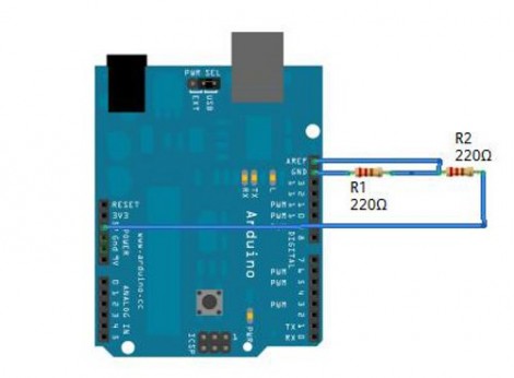
Little Bird Electronics posted an article about using an analog voltage reference with Arduino. This is a tool available when using an analog-to-digital converter. By setting up either an internal or external AREF, you can better use the ADC considering its resolution limitations. For instance, if you are measuring a signal that you know will always be below 2V, an external circuit, such as a voltage divider or an adjustable regulator, can give you a reference voltage just above that upper limit; say 2.5V. This way the 1024 divisions of resolution will be spread across your signal’s range, rather than just the lower half of the ADC readings.

Analog references are common to microcontrollers that have ADCs. Even if you’re not working with an Arduino, read through the article and use what you learn with your uC of choice.

Paper Touchpad

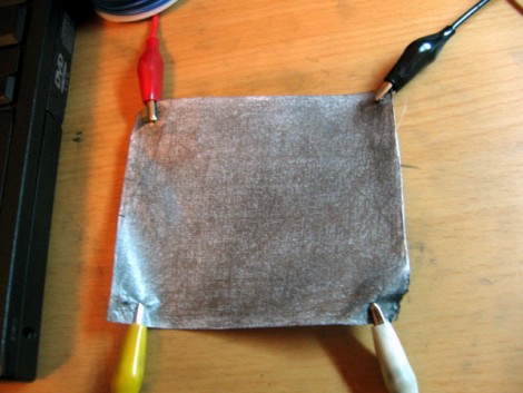
If you don’t mind getting your fingers a little dirty you can replace your mouse with a piece of paper. [Dr. West] made this touchpad himself, which measures signals at the corners of the paper using four voltage dividers. The paper has been completely covered with graphite from a pencil (which we see in hacks from time to time), making it conductive. The user wears an anti-static strap that grounds their hand, allowing an Arduino to calculate contact points on two axes when a finger completes the circuit. See this controlling a cursor in the video after the break.

Continue reading “Paper Touchpad”

Make Switched-mode Power Supplies Do Your Bidding

[Ken] needed to supply 3.3 volts of regulated power. He started by using a linear voltage regulator but after a few calculations he discovered that 72% of what he put in was lost to heat. The solution to this is a switched-mode power supply. Rather than burn off energy through a voltage divider, an SMPS turns the power on and off very quickly to achieve the desired voltage.

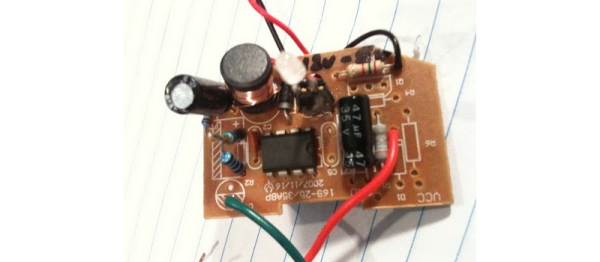
A car charger-type USB regulator was chosen as [Ken’s] donor device. He figured that making adjustments to the resistors inside would affect the output voltage and he was right. He adjusted the potential divider and ended up with a steady 3.295V.

We asked him to share the schematic that he put together from studying the board and he came through. See that and get the link to the DC-DC converter datasheet after the break. Continue reading “Make Switched-mode Power Supplies Do Your Bidding”

Reverse Engineering Apple’s Recharging Scheme

[vimeo=http://vimeo.com/13835359]

[Ladyada] has been hard at work reverse engineering the charging method used by Apple products. This saga takes us through the years as new devices were released and subsequently broke Minty Boost’s charging capabilities. It seems the data lines were gradually adopted as a means for iPhones and iPods to identify the charger that had been connected. By adding voltage dividers to the D+ and D- lines you can instruct the handheld to pull 1 Amp (with data voltages of 2.8v and 2.0v) for wall chargers or 0.5 Amps (2.0v on both data lines) for portable chargers. In the video above [Ladyada] removes the surface mount resistors from a commercial charger in order to measure the voltage divider and discover the secret.

Multiple Buttons And A Pot On one pin

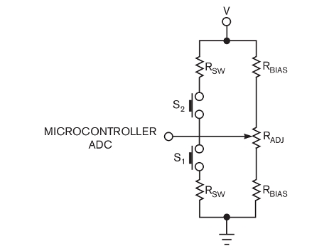
[Kevin Fodor] shares his method of reading multiple inputs on one pin of a microcontroller. The analog to digital convert function of the microcontroller is used to read a potentiometer but with some careful calculations a resistor network can be built into the circuit that provides a unique voltage value for each button pushed. The only real drawback is that the system cannot read multiple button presses at the same time. Theoretically up to ten momentary push buttons can be used but [Kevin] estimates that only four plus the potentiometer will work reliably.

[Thanks Charper]