Restoring A Jukebox With An Arduino

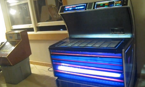
[Jim] just finished restoring an old Seeburg USC1 jukebox for his father using an Arduino, replacing an electromechanical rats nest of wires. The stack of 45 records were replaced with an Arduino Mega 2560 with an Sparkfun MP3 player shield, and he jukebox lights are now controlled with 74595 shift registers. Because his jukebox isn’t taking in money, the dollar bill validator has been modified into a ‘skip song’ button, and when there are no songs in the jukebox queue, there are 500 additional songs on the SD card that will randomly play.

We’ve seen one of [Jim]’s builds before. Earlier this year he repaired a thirty year old Pachinko machine using the same Arduino + MP3 shield setup. It looks like [Jim] is pretty skilled at revitalizing bulky old electronics. The jukebox restoration is great and has a lot more class than the internet-connected touch screen monstrosities that we still pump money into.

Check out the video after the break for a walk through of this restoration.

Continue reading “Restoring A Jukebox With An Arduino”

Electric Longboard Uses DIY Hub Motors

As a student of MIT, [Jed Storey] has access to a ton of machine tools, so he decided to build an electric longboard with hub motors by hand.  He wound up re-doing a lot of his project, so we can commiserate with him on the trials of R&D.

Inspired by the BWD scooter, [Jed]‘s longboard uses hub motors – the wheel is the motor. The rotors were fabricated in-house, and off-the-shelf stators were wound by [Jed] by hand. There’s a lot of work that went into this build, and the build log is really fascinating in this regard.

The board is controlled by a pistol-grip R/C controller that had been modified to include a dev board and an XBee. For power, an aluminum enclosure was fabricated, strapped underneath the deck, and filled with LiPo batteries. While the build is mostly done, [Jeb] is thinking about scrapping it and moving onto version 2, the HeavyBoard. Check out the video of the board in action.

Who Knew Jacob’s Ladder Builds Had So Many Options?

[Grenadier] has a thing for the high voltage and, as you can see, he’s found multiple ways to build the icon of HV toys – a Jacob’s Ladder.

The three look similar, but they use different means of generation the voltages necessary to get a spark to jump through the air. The exhibit on the left uses a neon sign transformer, the one in the middle is based on a transformer from an X-ray machine, and the example to the right uses a microwave oven transformer. [Grenadier] discusses the pros and cons of each method, then links to his in-depth posts about working with each one them. There are also videos for all three. We’ve embedded the video for the microwave oven transformer after the break. That version of the Jacob’s Ladder requires some way to start the spark and in the video he’s doing it manually. There is always the option to add a solenoid to do the job but he does mention that you can’t just let it run because that cheap transformer will burn out before long.

If you like what you see here, perhaps you’ll be entertained when he runs HV through some soda cans.

Continue reading “Who Knew Jacob’s Ladder Builds Had So Many Options?”

A Stackable Motor Driver Shield For The Arduino

The Arduino has been used for many purposes, and  “shields” are available to make many common tasks easier.  However, [Nick] wanted a stackable motor driver shield, so he build one himself!. There are many motor driver shields available for the Arduino, however, there aren’t any that allow one to drive as many motors as were needed for his project, and none that were stackable.

[Nick] had no experience designing and fabricating a custom board, but decided to try his hand at it anyway. Armed with a free version of [Eagle] PCB design software, he designed the board that he needed then sent it to [Seeed] to be manufactured. According to his article, a quantity of 10 Arduino-sized boards can be purchased for the price of $25. At that price point, some hobbyists may want to consider this option rather than manually creating their own circuit.

According to [Nick], he was able to manufacture his first board with no errors on his first run! Not bad for his first try at something like this.

DIY PCB Exposure Box Looks Professionally Made

diy_double_sided_exposure_box

[Stynus] was frustrated with the fact that he would have to flip his PCBs over mid way through the exposure process, so he decided the best course of action would be to build his own double-sided PCB exposure box.

He scored some UV LEDs on eBay, and after waiting a few weeks for PCBs to arrive, he was ready to start construction. The box contains a sliding glass shelf, which is positioned between two sets of LED panels. The setup lets him simultaneously etch both sides of any PCB, up to 20cm x 30cm in size. The exposure box is run by a PIC 16F628P and features an LCD status panel as well as a small handful of controls. [Stynus] programmed the box to retain the length of the last exposure, making it easy to replicate his results time after time.

Towards the end of the build log he shows off some pictures of the completed exposure box, which looks very professionally done. It’s a great job all around, and we would gladly take one for our workshop in a heartbeat.