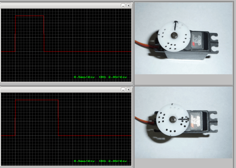
Servos seem to be the go-to option when adding motors to hobby projects. They’re easy to hack for continuous rotation for use in a robot, but with the control board intact they are fairly accurate for position-based applications. But do you know how the hardware actually works? [Rue Mohr] recently published an article that looks at the inner world of the servo motor.
As you know, these motors use a voltage, ground, and signal connection for control. The position of the horn (the wheel seen on the servos above) is dependent on that control signal. The duty cycle of a 20 ms pulse decides this. Inside the housing is a control board capable of measuring this signal. It’s got a chip that monitors the incoming PWM pulses, but that’s only half of the equation. That controller also needs feedback from the horn to know if its position is correct or needs to be changed. Integrated with the gear box that connects the motor to the horn is a potentiometer. It’s resistance changes as the horn turns. Knowing this, it is possible to fine tune a servo by altering that resistance measurement.


