Robot Battle For The Big Leagues: Valkyrie And The DARPA Challenge

valkyrieRobot

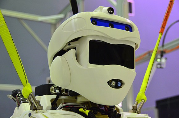
Even though NASA’s Johnson Space Center’s impressive build for the upcoming DARPA Robotics Challenge is one of many entries, it has to be one of the coolest. The gang at IEEE Spectrum got a sneak peak of the robot dubbed “Valkyrie”, which at 1.9m and 125kg boasts 44 degrees of freedom while managing to look like a finished product ready to roll off the shelf. We can expect to see other custom robots at the challenge, but a number of teams will compete with a Boston Dynamics Atlas Robot, which we’ve covered a couple times this year.

A few readers are probably polishing their pitchforks in anticipation of shouting “Not a hack!” but before you do, take a look at the tasks for the robots in this challenge and consider how new this territory is. To that end, the NASA JSC crew seem to have prepared for resolving catastrophes, even if it means throwing together a solution. They’ve designed the limbs for quick removal and even reversibility: the arms are identical and only slight adjustments are required to turn a left arm into a right. Unlike the Atlas, which requires a tether, Valkyrie is battery-operated, and it can run for around an hour before someone needs to crack open the torso and swap in a new one, Iron Man filmstyle.

The team was also determined to make Valkyrie seem more human, so they added a soft fabric layer to serve as a kind of clothing. According to IEEE Spectrum, it’s even getting custom made footwear from DC Shoes.There are some utilitarian compromises, though: Valkyrie has adopted a shortcut taken by time-constrained animators in many a cartoon, choosing three fingers per hand instead of four. Make sure you watch the video after the break for a closer look.

Continue reading “Robot Battle For The Big Leagues: Valkyrie And The DARPA Challenge”

Open Your Hackerspace Door With A Phone Call

elabHackerspaceDoor

[Mário] sent us a tip detailing the access control system he and his friends built for the eLab Hackerspace in Faro, Portugal. The space is located in the University of Algarve’s Institute of Engineering, which meant the group couldn’t exactly bore some holes through campus property and needed a clever solution to provide 24/7 access to members.

[Mário] quickly ruled out more advanced Bluetooth or NFC options, because he didn’t want to leave out members who did not have a smartphone. Instead, after rummaging around in some junk boxes, the gang settled on hacking an old Siemens C55 phone to serve as a GSM modem and to receive calls from members. The incoming numbers are then compared against a list on the EEPROM of an attached PIC16F88 microcontroller, which directs a motor salvaged from a tobacco vending machine to open the push bar on the front door. They had to set up the motor to move an arm in a motion similar to that of a piston, thus providing the right leverage to both unlock and reset the bar’s position.

Check out [Mário’s] blog for more details and information on how they upload a log of callers to Google spreadsheets, and stick around for a quick video demonstration below. If you’d prefer a more step by step guide to the build, head over to the accompanying Instructables page. Just be careful if you try to reproduce this hack with the Arduino GSM shield.

Continue reading “Open Your Hackerspace Door With A Phone Call”

Bizarre Mini Amplifier + White Noise Generator?

bma_finished_a

[Jordi] made this awesome looking mini amplifier which has a rather unusual feature. He’s calling it the Bizarre Mini Amplifier because it also has a white noise generator built right into it! Bizarre right?

Now, most people would just find a suitable amplifier and put it into a nice box, but not [Jordi]! He’s designed the amplifier circuit from the ground up! It features four distinct stages like most typical amplifiers:

  1. Impedance Adapt Stage: Two OPAMPS for both the left and right channels — The high input impedance allows for different audio sources to be connected without affecting the output.
  2. Mixer stage: Combines the left, right and noise signals into one, using a third OPAMP. A potentiometer is the output resistor which allows for the volume control.
  3. Filter Stage: A simple filter stage that uses a R-C low-pass filter, another potentiometer controls the tone.
  4. Power Stage: A final power amplifier to boost the output.

After building the circuit, there was a bit of troubleshooting to get it to work properly, so if you’re interested [Jordi] has done a great write-up of this on his blog.

Finally, he decided to add a white noise generator after he discovered it helps him sleep. This is the one part of the project that he didn’t actually go into detail for! But, considering it’s just white noise, we could probably figure out what he did. Stick around after the break to see the device in action!

Continue reading “Bizarre Mini Amplifier + White Noise Generator?”

Turning A Building Into A Rubik’s Cube

cube

[Javier] must have an awesome academic adviser. For his master’s thesis, he turned a building into a Rubik’s cube.

The Ars Electronic Center in Linz, Austria, is a building with a whole bunch of colored, programmable lights on the facade. [Javier] thought this would make for an excellent Rubik’s cube, and set to work convincing his thesis advisers this idea was possible, and building the hardware and software.

Since only two sides of the building are visible at any one time, [Javier] needed to build a controller for this project. The solution was to build a normal Rubik’s cube and stuff a microcontroller and a FreeIMU in the center. This setup senses the twists and turns of the Rubik’s cube, as well as it’s position in space, effectively creating an interface between the hand and a giant light-covered building.

The Rubik’s cube interface connects to a computer running an app written in openFrameworks. By sensing the direction the cube is oriented, it can automatically display the two sides of the cube facing the user.

There’s a great video showing just how this building-sized Rubik’s cube works. You can check that out below.

Continue reading “Turning A Building Into A Rubik’s Cube”

Mains Frequency Display

[James] lives in the UK where the frequency of electricity is suppose to be 50Hz, but it tends to fluctuate based on supply and demand. He decided he wanted a display to track this.

Now, the National Grid Website shows a real-time graph of the last 60 minutes. But that’s way too easy. Time to bust out the soldering iron!

Armed with pencil and paper [James] scribbled down some ideas on how to count the frequency — he settled on counting 200 cycles, which means that at 50.000Hz, it would take exactly 4 seconds. The next problem was getting a timing source that was accurate enough for the job. An ATtiny84 wouldn’t do the trick (too inaccurate), nor would an external crystal (too expensive) — But a real-time clock? That’s the ticket! He’s using a DS3231 RTC chip, which at +/- 2ppm 32.768kHz is more than precise enough.

Some math, programming, and soldering later and the display is complete! He’s even added an up/down arrow to show the most recent trend of the electricity.

Nice one [James]! Last year [Ch00f] did a similar project, where he tore down a 194 discrete transistor clock kit to see how it worked — as an aside, he needed to know how accurate the 60Hz coming out of his wall was!