Retro Chaser Sign Lights Up Your Life

lighted-sign

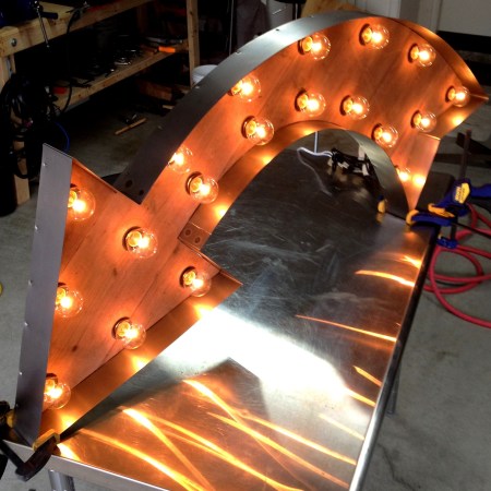
[Gnsart] builds props often used in the film industry. He’s created an amazing retro Vegas style light chaser sign. The sign was started as a job a few years ago. While [Gnsart] could handle the physical assembly, the cost of a mechanical light chaser pushed the project over budget. The sign project was cancelled back then, but he never forgot it.

Fast forward to a few weeks ago. [Gnsart] happened upon the Arduino community. He realized that with an Arduino Uno and a commonly available relay board, he could finally build the sign. He started with some leftover cedar fence pickets. The pickets were glued up and then cut into an arrow shape. The holes for the lights were then laid out and drilled with a paddle bit. [Gnsart] wanted the wood to look a bit aged, so he created an ebonizing stain. 0000 steel wool, submerged and allowed to rust in vinegar for a few days, created a liquid which was perfect for the task. The solution is brushed on and removed just like stain, resulting in an aged wood. We’ve seen this technique used before with tea, stain, and other materials to achieve the desired effect.

[Gnsart] then built his edging. 22 gauge steel sheet metal was bent to fit the outline in a bending brake. The steel sheet was stapled to the wood, then spot welded to create one continuous piece. Finally, the light sockets were installed and wired up to the Arduino. [Gnsart] first experimented with mechanical relays, and while we love the sound, we’re not sure how long they’d last. He wisely decided to go with solid state relays for the final implementation. The result speaks for itself. LEDs are great – but there is just something about the warm glow of low-wattage incandescent lights.

Continue reading “Retro Chaser Sign Lights Up Your Life”

The Berkeley Tricorder Is Now Open Source!

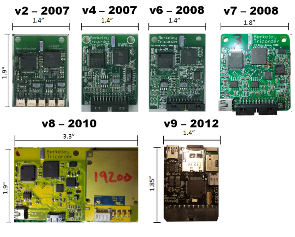
[Reza Naima] has just released the designs for his Berkeley Tricorder for the public to use. He’s been designing it since 2007 as his thesis work for his PhD, and since he’s done now (Congrats!), he decided to let it grow by making it open source!

We covered it almost 7 years ago now when it was in its first prototype form, and it has come a long way since then. The latest version features an electromyogram (EMG), an electrocardiograph (ECG), a bioimpedance spectrometer, a pulse oximeter, an accelerometer, and all the data is recorded to a micro SD card or sent via bluetooth to a tablet or smart phone for data visualization.

He’s released it in hopes that other researchers can utilize the hardware in their own research, hopefully springing up a community of people interested in non-invasive health monitoring. With any luck, the development of the Berkeley Tricorder will continue, and maybe some day, can truly live up to its name!

Unfortunately there’s no new video showing off the latest iteration, but we’ve attached the original video after the break, which gives a good narrative on the device by [Reza] himself.

Continue reading “The Berkeley Tricorder Is Now Open Source!”

Testing The Limits Of Home PCB Etching

[Quinn Dunki]’s Veronica, a homebrew computer based on the 6502 CPU, is coming along quite nicely. She’s just finished the input board that gives Veronica inputs for a keyboard and two old Nintendo gamepads. [Quinn] is building this computer all by her lonesome, including etching all the PCBs. She’s gotten very, very good at etching her own boards, but this input board did inspire a few facepalming moments.

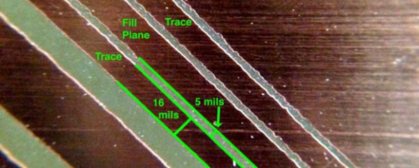
In an earlier post, [Quinn] went over her PCB etching capabilities. As demonstrated by the pic above, she’s able to print 16 mil traces with 5 mil separation. This is just about as good as you can get with homebrew PCBs, but it’s not without its problems.

[Quinn] is using a photographic process for her boards where two copies of a mask is printed on an acetate sheet, doubled up, and laid down on a pre-sensitized copper board. The requirement for two layers of toner was found by experience – with only one layer of toner blocking UV light, [Quinn] got some terrible pitting on her traces and ground planes.

Two photographic masks means the masks must be precisely aligned. This example shows what happens when the acetate sheets are ever so slightly misaligned. With a 5 mil gap between traces, [Quinn] needs to align the masks to within ±2.5 mils; difficult to do by eye, and very hard once you factor in flexing and clamping them down to the copper board.

Even when this process goes perfectly, [Quinn] is pushing the limits of a laser printer. When printing at 600 dpi, the pixels of the print are about 1.5 mils. While GIMP, printer drivers, and the printer itself have some fancy software to help with the interpolation, [Quinn] is still seeing ‘bumps’ on the edges of perfectly aligned parts. This is one of those things that really makes you step back and realize how amazing fabbing PCBs at home actually is.

With most of the hardware for Veronica out of the way, it’s just about time for [Quinn] to start programming her baby. We’re not expecting a full-blown operating system and compiler, but those NES gamepads are probably crying out for some use.

International Obfuscated C Code Contest Winners Posted

ioccc

The International Obfuscated C Contest – the contest to create the most useful, useless, or unique program in absolutely unreadable C code – has just posted the winners of the 2013 contest.

Of the entries of note, a few really stand out. The pic at the top of this post, for instance, comes courtesy of this submission. It’s an iterative ray tracer stuck inside an infinite loop that, when left running overnight, is able to produce amazing renders.

An IOCCC contest wouldn’t be complete without some ASCII art C code, and this entry fits the bill. It’s a Tetris painting tool that creates images made out of tetronomoes. Each image is built up one line at a time from the bottom up, using Tetris’ lack of physics to create a picture out of un-cleared lines.

One of the most impressive entries for this (last?) year’s contest is a tiny 8086 PC emulator/virtual machine written in only 4043 bytes of code. It’s a fully functional 80s-era PC emulator that can run vintage copies of AutoCAD, Windows, Lotus 1-2-3, and SimCity.

All the submissions are awesome, but like any IOCCC contest, there aren’t actually any winners. Or they’re all winners. The Obfuscated rules aren’t very clear in that regard.

Ninja-Drillpress-Skills Produced This Glow Plug Extruder

step5_5e1

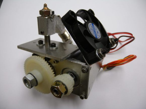
Still looking to make your own 3D printer? Don’t have many tools or a big budget? Well, [Adam Kemp] has just the hack for you — a DIY extruder that can be made with only a drill press and a few hand tools.

First, a little background. [Adam] loves the nitty gritty side of 3D printing, so he’s managed to build his own printer almost completely out of recycled parts from printers, scanners, etc. Unfortunately, there’s not much of an option when it comes to the extruder. Almost all designs online feature 3D printed parts. Not wanting to admit defeat, he came up with this clever glow plug extruder design.

As you can imagine, it requires a lot of drilling, and it would be a heck of a lot easier on a mill — but that’s not the point here. He even goes into detail on how to hob the extruder feed wheel using nothing but a tap, a drill press, some skateboard bearings, and a few washers and nuts. The entire guide is great, so if you want to feel like MacGyver for a few hours and you need a good extruder, try it out! 

To see the extruder in action, stick around after the break.

Continue reading “Ninja-Drillpress-Skills Produced This Glow Plug Extruder”

Build A Simple Audio Amp

[Ynze] has built an audio amplifier that looks and sounds great. His amplifier uses a National Instruments (now TI) LM3886 Overture series 68 Watt power amp. The LM3886 places [Ynze’s] amp squarely in the “Gainclone” catagory. Gainclone or Chipamp are terms long used by the DIY community to describe audio amps based upon highly integrated semiconductor amplifiers. The Gainclone name stems from the original Gaincard audio amplifier sold by 47 labs. The Gaincard used less than $100 USD of parts when it was introduced in 1999. It sounded good enough to command a $3300 USD price tag on the audiophile market. The low parts count and simple construction spawned the audio DIY community to build their own versions of the Gaincard. Hundreds of variants exist now, and wading through the different versions can be a bit of a daunting task. [Ynze] found a basic design that works, and built from there.

One of the interesting things about [Ynze’s] amp, as well as many of the Gainclones, is the fact that they use no circuit board. All wiring is done point to point. resistors are soldered directly to the pins of the amplifier chip. This can be some tricky soldering for beginners, but several PCB kits are available. [Ynze] built his amp in two cases. One case holds the power supply, and the other contains the amplifier itself. [Ynze] is using a large toroid transformer to drop his local 230V mains down to +25V and -25V. The amplifier circuit itself is simple – a few discrete components surround the LM3886 and it’s heat sink. [Ynze] also did some very nice carpentry work on his wood chassis. The resulting amp looks like it’s right out of the 1960’s – but hides 1990’s electronics inside.

Continue reading “Build A Simple Audio Amp”

Interfacing With The HTC Desire Display And Its Touch Panel

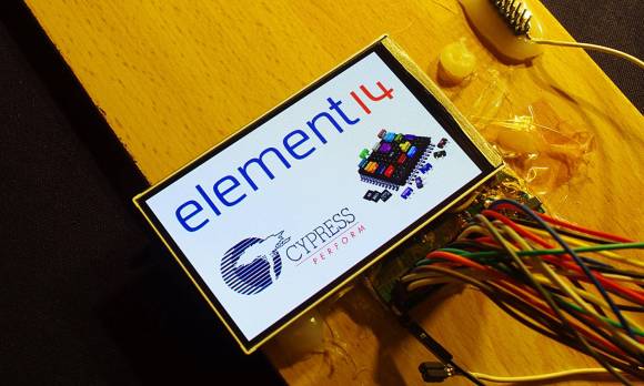
Part of [Linas]’ submission to last year’s Cypress Smarter Life Challenge involved using the HTC Desire display and its touch screen. This particular phone includes a full-color active-matrix OLED (AMOLED) display that has a 3.7″ diagonal and a 480×800 resolution, resulting in a 252ppi pixel density. Using a MSO2024B oscilloscope, [Linas] originally started his adventure with the touchscreen by sniffing the I2C signals. As some math was required to extract the data, he later found the HTC Desire source code and included it on his STM32F429 (so much for reverse engineering!).

After spending many hours searching for the AMOLED display and controller datasheets, [Linas] resorted to pay a company to get the resources he needed. He produced a custom-made PCB to provide the display with the required voltages, as well as offering a 0.1″ connector to interface with it. A RGB565 interface is used to communicate with the screen so only 65k out of the 16 million colors are used. You may download all the program files and datasheets in [Linas] write-up.