Most of the electric motors we see these days are of the electromagnetic variety, and for good reason: they’re powerful. But there’s a type of motor that was invented before the electromagnetic one, and of which there are many variations. Those are motors that run on high voltage, and the attraction and repulsion of charge, commonly known as electrostatic motors.
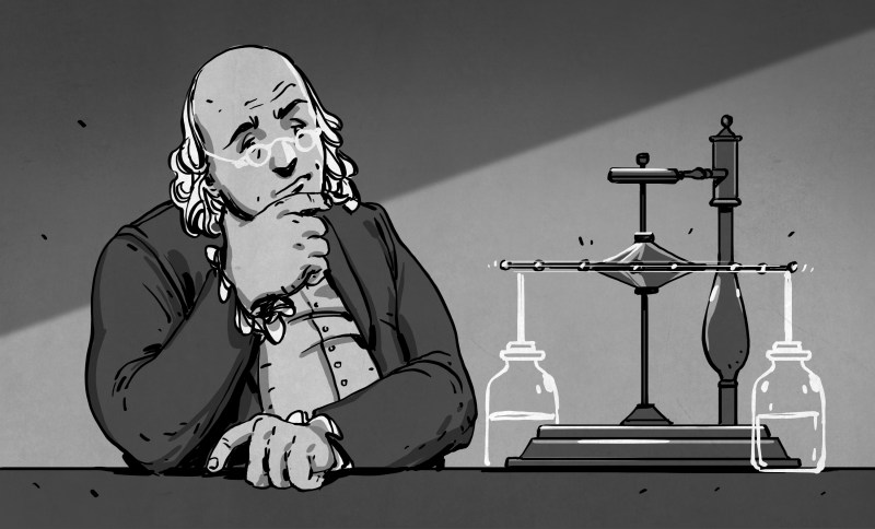
Ben Franklin — whose electric experiments are most frequently associated with flying a kite in a thunderstorm — built and tested one such high-voltage motor. It wasn’t very powerful, but was good enough for him to envision using it as a rotisserie hack. Food is a powerful motivator.
What follows is a walk through the development of various types of these motors, from the earliest ion propelled ones to the induction motors which most have never heard of before, even an HV hacker such as yours truly.
Franklin’s Electric Wheel
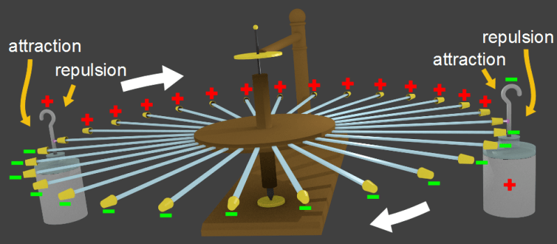
In 1748, Benjamin Franklin invented what he called the electric wheel. This is usually cited as the first electrostatic motor and sometimes as the first electric motor, depending on your definition. The rotor consisted of a wooden hub with 30 glass bars attached to the circumference. These bars were strips cut from window glass. Brass thimbles were attached to the end of each bar. To turn easily, the rotor had a central shaft with an iron point on the bottom and a strong wire at the top, the wire going through a hole to keep it all upright.
The power source consisted of two oppositely charged Leyden jars, the original name given to a cylindrical capacitor made using a jar of some sort. The jar, and therefore the dielectric, was glass in Franklin’s day. A wire extended up from the inner capacitor plate and this wire was placed near where the thimbles would pass by. As a thimble passed, a spark would occur between the thimble and the wire, charging the thimble with the same polarity as the inner plate. Being like-charged, the thimble would be repelled from that wire, turning the wheel. As the thimble reached the wire of the opposite Leyden jar, being of opposite charge, it would be attracted to the jar’s wire. As it passed, a spark would occur between the two, charging the thimble to the same polarity as that wire and causing it to be repelled, turning the wheel some more.
The initial direction of the wheel was set by giving it a push by hand. In a letter (page 29), Franklin wrote that it rotated at 12 to 15 RPM, bearing the weight of one hundred Spanish dollars. He also wrote that:
if a large fowl were spotted on the upright shaft, it would be carried round before a fire with a motion fit for roasting.
Electric Whirl
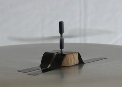
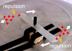
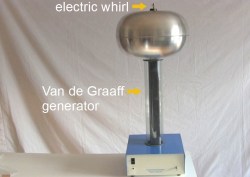
This motor is a bit older than Franklin’s and dates back to 1745. It was made by Andrew Gordon, a Scottish Benedictine monk. It goes by many names but the original name was the electric whirl. The basic idea is that an electric field at a sharp point will be stronger than at a smooth point. This strong electric field ionizes the air near the point, and depending on the polarity, may even emit electrons to the air. This ionized air is called a corona. In either case, the ionized air around the point has the same polarity as the material making up the sharp point. Since like-charges repel each other, the ionized air repels the sharp point. You’ve of course heard of Newton’s third law which basically states that for every action, there’s an equal and opposite reaction. So the air is repelled in one direction, and the sharp point reacts by being repelled in the other direction. Arrange the point on an arm which is free to move around an axis, and the arm will rotate around that axis. The moving ionized air is often referred to as ion wind and for that reason this is also often called an ion wind rotor, or ion wind spinner or pin wheel.
Usually there are two points, each on their own arms, pointing in opposite directions to make for a more stable system. There can of course be more. The one pictured here is sitting on top of a Van de Graaff generator’s dome, which is at high voltage with respect to ground. The electric whirl is in electrical contact with the dome through the supporting shaft. The other end of the electric field is the surrounding air, the bottom of the Van de Graaff generator and the room.
Poggendorff/Corona Motor
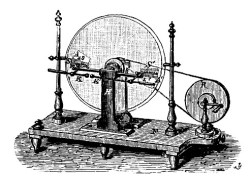
The 1860s was a time when many were experimenting with influence machines, machines that used electrostatic induction, called influence at the time, to produce high voltages. One such experimenter was Wilhelm Holtz. In 1867, in a stroke of brilliance, he connected the output of a similar machine to one of his and found it would run as a motor. And so in 1869, J.C. Poggendorff had a simplified version of Holtz’s machine built that had only what it needed to run as a motor.
Poggendorff’s motor consisted of a glass disk with combs facing it on either side. The combs had sharp points on them arranged so that the points would be near the disk but not touching. The combs could be turned so that they were strictly radial with respect to the disk. In this case the disk was not self-starting and, once given a spin by hand, would continue to rotate in that direction. However, the combs could also be turned to an off-radial angle. In this case the disk would self-start and be unidirectional.
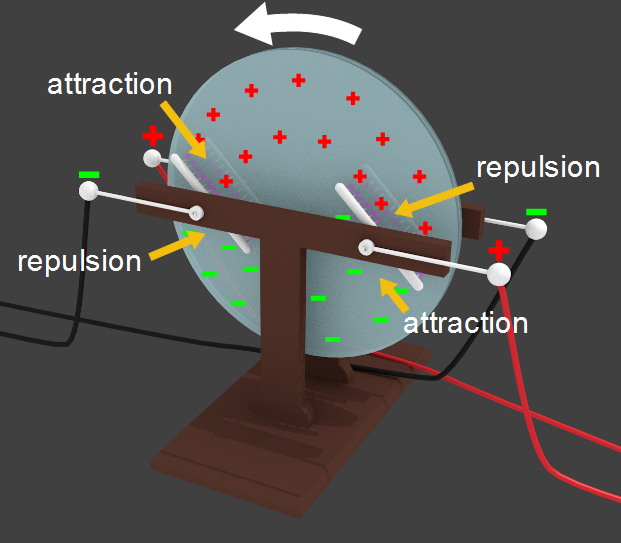
One difference between Franklin’s wheel and Poggendorff’s motor is that Franklin’s places charge onto the thimbles using a spark, whereas Poggendorff’s sprays charge onto the disk through ionized air, or a corona. This corona is the same we mentioned when talking about the electric whirl, and is formed in the same way — the sharp points result in a strong electric field which ionizes the air.
Similar to Franklin’s the area of the disk, approaching a comb is charged with the opposite polarity with respect to the comb, and so is attracted to the comb. And the area moving away from the comb is charged with the same polarity, and so is repelled.
Poggendorff’s motor also has some advantages over Franklin’s electric wheel. The combs are always spraying onto the disk, continuously producing rotation, whereas with Franklin’s, this happens only when a thimble passes a Leyden jar. Also, there is always the same amount of disk surface area facing the combs, resulting in a constant torque being produced.
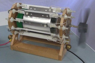
Due to the corona being the mechanism for transferring the charge, these types of motors are generally called corona motors. And in many of them the disk is replaced with a cylinder. The combs then become either just the sharp ends of thin wires or long sharp blades as in the one shown here that was run off of atmospheric electricity.
Capacitor Motors
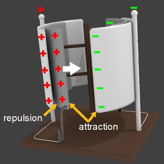
This next type of motor was invented in 1889 by Karl Zipernowsky, but an easier version to illustrate is a 1904 one by N.G. van Huffel[1]. In it the rotor and stator are both made up of two partial cylinders, or curved plates. The rotor plates have a slightly smaller diameter to fit inside the stator plates.
The stator plates are charged oppositely and the rotor plates receive a charge from their adjacent stator plates via a sliding contact just as they are rotating away from those plates. That way they repel away from the adjacent stator plate and reach a position where they’re then attracted to the next stator plate.
The big difference between all these motors is in the way the charge is moved around, via sparks as in Franklin’s, via corona, or via sliding contacts. However, since sliding contacts are used here, these motors can run at a lower voltage than the others. These can also run on AC.
Induction Motors
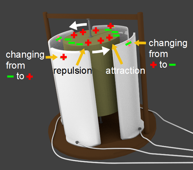
The induction motor is the one that operates on perhaps the most interesting principle. The rotor is not electrically connected to any power supply and is made of a dielectric material. The surrounding stator plates are supplied with AC, and so there is a rotating electric field surrounding the rotor. That electric field induces polarization of the molecules on the surface of the rotor. From the stator’s point of view, this appears as a net charge.
The key is that as the stator plates’ fields change polarity, it takes time for the polarization of the nearby rotor to change in response. That creates a lag between the moving field and the polarized molecules. That lag is what causes the rotor to follow the field.
The illustration shown here is of one made by Rocardo Arno in 1892-1893[1].
Where Have All The Motors Gone?
As we said, electromagnetic motors are far more powerful. But electrostatic motors do find use in MEMS motors of microscopic dimensions. And of course, they haven’t really gone anywhere if you consider electrostatic tinkerers who love resurrecting these old mechanical marvels. I’ve dabbled in electric whirls and corona motors and have thirty thimbles on order from China for something which the attentive reader can guess at. What electrostatic motors have you toyed with in your home laboratory?
Resources:
[1] Electrostatic Motors: Their History, Types and Principles of Operation by Oleg D. Jefimenko


They’re not gone. There’s some work in Madison, WI that’s making electrostatic machines with torque densities similar to industrial magnetic motors. Both a company and a professor at the University of Wisconsin.
http://www.c-motive.com/
http://ludois.wempec.wisc.edu/electric-machines/
Awesome.
“To produce more torque and transition to a competitive position, an electrostatic machine must possess a large rotor-stator surface area immersed in a dielectric medium to store electric charge under high potential. Our group uses dielectric liquids, 3D printed structures with high surface area, and medium voltage power electronics to develop high torque electrostatic machines for low speed direct drive applications.”
Ladies and gentlemen. Start your 3D printers!
The thing is, in practical applications like electric cars, torque density isn’t the foremost concern.
Torque is linearily proportional to the current, while the ohmic losses are proportional to the square of current, so halving the torque and doubling the speed of the motor reduces the ohmic losses by 75%. Likewise, halving the speed and doubling the torque increases losses by 300%.
The amount of copper and magnetic materials are also reduced when the motor is built to run faster, so it becomes smaller and lighter – if the speed of the motor isn’t constrained, then the power density of the motor becomes inversely proportional with its torque density – and power can always be transformed into torque via gears.
I once loosely wrapped one end of a piece of 30AWG wire around the output of a flyback transformer and bent the other end at an angle. Power it up and the piece of wire started spinning surprisingly quickly.
[comment about what a friend used to do on a larger scale deleted]
“You’ve of course heard of Newton’s third law which basically states that for every action, there’s an equal and opposite reaction. ”
Wait! Wait! What? There’s a third one? :-D
Seriously there’s one obvious thing about electrostatic motors especially relevant for their time. Ease of design and construction.
Yup, there’s a third one. https://en.wikipedia.org/wiki/Newton's_laws_of_motion Possibly you’re forgetting number two, F=ma. Not as fun as one and three. I think of it sometimes when walking across an intersection and I suspect the stopped car (massive object) is about to accelerate. In that case, even at a low acceleration F can at least roll you onto the windshield.
F=ma is ok, but with all the trendy electronic health/wellness stuff people seem to be more interested in W=mg. :)
Clearly, I have not made enough!
I feel pretty cheated though, that in an entire class on electromagnetic machinery I was not once introduced to these historical marvels.
The Oxford electric bell have run for 177 years: https://www.youtube.com/watch?v=r_jlZWbo33M which in this definition is a linear electrostatic motor.