
Even before the Industrial Revolution, gears of one kind or another have been put to work both for and against us. From ancient water wheels and windmills that ground grain and pounded flax, to the drive trains that power machines of war from siege engines to main battle tanks, gears have been essential parts of almost every mechanical device ever built. The next installment of our series on Mechanisms will take a brief look at gears and their applications.
Spurring Progress Along
As is often the case, evolution is the best inventor, and a geared mechanism linking the rear legs of juvenile planthopper insects predates the human invention of gears by a couple of billion years. Human use of gears dates back at least to third-century BC China, and the technology spread rapidly and widely. Within a few hundred years, precisely machined metal gears had enabled complex geared devices like the Antikythera mechanism to be built in Greece.
At its simplest, a gear is nothing more than a wheel with some sort of teeth cut into its circumference. The teeth are sized and shaped to mesh with teeth on other mechanical elements to transmit torque. Multiple gears connected in series are called a gear train, and if the diameters of gears in the gear train are different, the torque transmitted will be proportional to the difference. So, if the driving gear has a diameter of 1 cm and the driven gear is 10 cm across, the gear train will increase the torque 10-fold while reducing the rotational speed by a factor of 10.
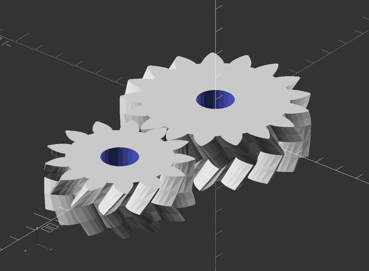
To counter this, teeth can be cut at an angle to the axis of rotation. Skewing the teeth like this around the circumference of the gear results in a helical pattern, hence the name helical gear. Not only are helical gears quieter, they can also be crossed to transmit power at a right angle. The tradeoff is that because of the skewed teeth, helical gears impart thrust along their axes. The thrust can be dealt with using thrust bearings, like tapered roller bearings, or by using two helical gears with opposing teeth directions on the same shaft to cancel out the axial thrust. This results in the beautiful herringbone gear seen in many high-power applications like wind turbines.
Powdered Gears
For the longest time, producing metal gears was a complex process involving multiple machining steps to produce teeth with the desired geometry. Teeth can be cut by any number of machining operations, like broaching, milling, shaping, or grinding.
But gear cutting is time-consuming and expensive, so most gears these days are produced by some kind of molding operation. Plastic gears of the kind we hate to see when we look inside a power tool built to a price point are easily produced by injection molding, and despite their bad reputation, they can result in perfectly serviceable if not particularly long-lived gear trains. But metal gears can also be molded, with powdered metal gears now making a huge share of the market.
Powdered metal gears are produced by filling a mold with very fine metal alloy powder mixed with binders and lubricants. The powder in the mold is compressed by a hydraulic ram with a tool matching the shape of the mold, and the tremendous pressure fuses the metal particles together into a solid strong enough to be handled. The green parts are then heated to permanently fuse the particles into the final metal part which in many cases is ready to use with no further machining.
https://www.youtube.com/watch?v=s1TGXa3pB5M
Roll Your Own
While powder metallurgy is out of reach for most home shops, DIY gears are very much doable by anyone with access to some basic machine tools. We’ll never get enough of watching [Chris] machine the gears and pinions of the Clickspring clock, and while those gears are highly specialized for the world of metrology, many of the same principles apply to gears for other applications. 3D-printing is making custom gear trains possible too, and the results can be surprisingly robust under the right conditions. And don’t forget CNC routers, which are turning out gears large and small in all sorts of materials.
It’s hard to even scratch the surface of what goes into the engineering behind gears — tooth geometry, pressure angles, lines of contact — nor can we cover the really interesting gears, like harmonic drives and epicyclic gears. But this is a start at least, and a taste of what you’re in for when you start adding gears to your builds. Open the floodgates of awesome gear projects in the comments!


If we are talking about the DIY gears, Cage gear is quite easy to make out of wood, with simple tools:
https://en.wikipedia.org/wiki/Gear#Cage_gear
Huh, I’ve never heard that term for those. I’ve heard lantern gear, and pin gear for when only one side is closed. One of the (admittedly few) good qualities of those is that when a tooth breaks, it’s very simple to swap it out instead of replacing the whole mechanism.
A blast from the past…
https://hackaday.com/2010/06/30/how-to-design-your-gears/
Yeah, I notice there’s occasionally been posts about circuits and computers around here too.
does someone have the link to the amazing collection of specialised gears? I believe I remember right that they were near ready to use in 3D printing (templates and the like).
“But gear cutting is time-consuming and expensive, so most gears these days are produced by some kind of molding operation. Plastic gears of the kind we hate to see when we look inside a power tool built to a price point are easily produced by injection molding, and despite their bad reputation, they can result in perfectly serviceable if not particularly long-lived gear trains. But metal gears can also be molded, with powdered metal gears now making a huge share of the market.”
Casting:
http://www.gearsolutions.com/article/detail/6301/casting-forming-and-forging
The gears used by Chris on Clickspring are being used in Horology, the study and measurement of time, not Metrology, the study of measuring anything (typically physical dimensions)
Buy it could easily be argued that horology is a subset of metrology, as metrology includes frequency standards therefore clocks.
John is half right. Gears in both Clickspring’s horology (watch and clock making) AND often metrology (science of mensuration- measurement, ie gauges and measuring equipment) both use a type of gearing called cycloidal gearing, meant for accuracy and smoothness of movement, for as much smooth and uninterrupted transmission of motion as possible. In horology, this is to mete out movement accurately in the form of devices for timekeeping that require this. In metrology, this is the same case because it provides accurate positioning for movement applied to gears for things needing high accuracy of movement with low force- much of dial gauges and measuring equipment, where lost gear motion would equate to lost distance measurement on measuring tool readouts.
Most gears in the world, regardless of their style of mesh (ie herringbone, spur, etc) are actually another form of tooth profile called involute gearing. This type of gear is meant for maximum power transmission with the least amount of wear, without the concern of movement accuracy as paramount. This is because in most applications, gears are used to transmit power, rather than accuracy of direct movement. These gears are the form in your car transmission, power tools and machinery. They don’t work well in timepieces- except they are often used in the winding gear trains of clocks and watches for this reason, just not the gears that make up the timekeeping train, that are normally moving to keep time.
Does this make sense? 2 kinds of gearing in the world (except for rare exotic forms rarely used)- involute (for power transmission, used in 99% of gear uses) and cycloidal (used in timekeeping gear trains and precision measuring instruments for accuracy, smoothness, and regularity of movement). Epicyloidal gears are internal gear versions of cycloidal gears.
I know this as a trained watchmaker.
That moment when the occasional offhand comment teaches you way more than the “executive summary” of content-free bullet points masquerading as an article…
Thanks, I try :D This is complicated stuff to really understand and I feel there is a lack of people who have the understanding and can summarize it in an intelligent way for people who don’t. Precision gearing is a very cool topic, if you want to learn more, the book Wheel and Pinion Cutting in Horology by Malcomb J Wild is good for cycloidal gearing theory, Gears and Gear Cutting by Ivan Law is good for normal involute gearing. If you really want to go off the deep end, the most approachable and comprehensive is Gears for Small Mechanisms by W.O. Davis. I own all of these given what I do.
The pressing and sintering video shows manufacture of sprockets, not gears. Sprockets aren’t used to drive each other directly, they’re used with chains. How about a HaD article on sprockets vs gears?
Won’t anyone think about Cogswell’s Cogs?
Because we all prefer Spacely Sprockets.
JETSON!!!!!!!
Yes boss, I mean yes Mr. Spacely sir!
If the series continues with more background on gears, then some info about various kinds of anti-backlash gears would definitely be in order. Then there are ‘linear gears’, AKA ‘racks’.
Nah, they just make an entry-level articles and then you can satistfy your curiosity elsewhere. Those articles are for beginners who don’t know anything about a topic. It’s good, but if you really want to learn about something, you must do it in true hacker way and learn yourself. Don’t just do one google search, do real depth searching, read some articles and then search some more.
I remember watching the press operator clean the old duplicator presses at the printing company I worked at.
That thing was FULL of powdered gears. And a lot of paper dust. And a lot of other dust.
I was watching some videos on casting a few days back and came across this: https://www.youtube.com/watch?v=OxpYLPF931g&t=3s
I’m also going to drop a line for a reference to magnetic gears: https://en.wikipedia.org/wiki/Magnetic_gear
I replaced the cam drive chain in my Moto Guzzi with gears, and fortunately they were steel, rather than another popular and cheaper set of case hardened aluminium. Owners of the aluminium types were disappointed when their gear sets wore out early because of poor installation – they were designed to run in a deeper oil bath than the steel sets, and when they weren’t, they suffered from a degenerative condition called brinnelling – wear from microwelding when boundary lubrication is missing, i.e. no oil bath. The metal surfaces of the gear teeth in direct contact with each other would weld together in microscopic spot-welds, then be torn apart as the teeth rotated away from each other – eventually leading to a loss of the case-hardened surface, sloppy gears, and consequently poor valve train performance. I’m glad I got a steel set.
I had some success laser cutting gears from plywood. My cocktail robot uses them to flip over bottles: https://hackaday.io/project/27966-flipper
The rack is even only made out of poplar but driven via a 3 to 1 reduction made out of birch ply by a NEMA23 stepper.
If space is available the weakness of the wood can easily worked around by choosing a larger diameter and modulus.
Obviously laser cutting is limited to spur gears.
Is it really limited to spur gears? I mean, obviously yes, but if you stack thin spur gears, with some cleanup, you might be able to make a worm drive or helical gears.
It is probably easier to laser cut a lathe and then create your worm gears with that. Spur gears is what can be done easily with a laser cutter. And they may become handy when creating the gear train for the thread cutting feature of your new lathe, though.
“[A] geared mechanism linking the rear legs of juvenile planthopper insects predates the human invention of gears by a couple of billion years.”
Billion might be an exaggeration, no? The first multi-cellular organisms formed ~600 million years ago, and I don’t think a whole lot of those had gearboxes.
Probably an imperial/metric thing – maybe they were “dog years”…
I’ve played with gears a couple times- first to make a unique extruder for a 3D printer – counter rotating nuts roll threads into 3 mm filament and push it into the hot-end (https://www.thingiverse.com/thing:261037), and most recently to make a belt lifted Z axis for a 3D printer (using a worm gear reducer to prevent the bed from dropping when power to the motor is cut).
The worm gear reducer works well, but it was expensive (OnDrives Rino: $140) so I’m waiting on some gears to arrive so I can test a printable worm gear reducer ($40) I designed. Expect a blog post and probably a hackadayio post about it when the gears finally arrive.
3D printing makes it surprisingly easy to do things with gears.
Could someone do an article on building gear *boxes* instead of just the gears?
The details of arranging the axles and the precision aspects of how to adjust spacing for acceptable friction seem to be taken for granted when the focus is only on the gears themselves.
High quality spur and helical gears in industry are generally made by hobbing, where a toothed cutter with a spiral track of straight-sided teeth rotates in a fixed ratio to the gear blank. This generates the correct involute tooth form for any number of teeth.
This used to be difficult, but with CNC it is now achievable in a modest home workshop. All you need to do is turn the gear blank at a proportion of the spindle speed. Add an encoder to your spindle and a bit of logic between there and a stepper (or servo) driver and you are good to go.
Here is a video I made several years ago showing exactly this approach. It makes gears in minutes. https://www.youtube.com/watch?v=ZhICrb0Tbn4