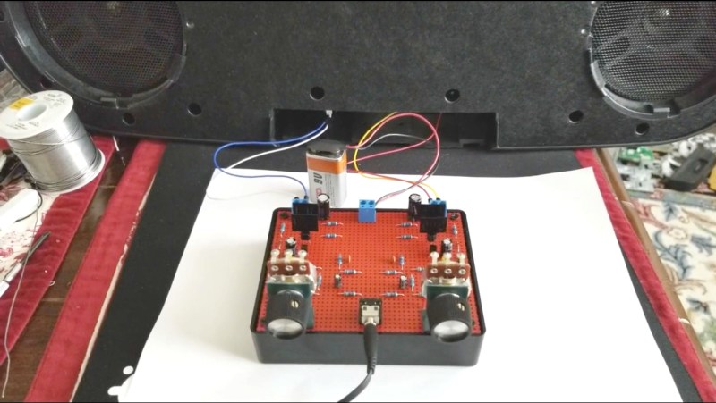
Reading an article about the first transistorized Hi-Fi amplifier, [Netzener] got the itch to make one. But what to use for the starting point? Enter an old Radio Shack P-Box stereo amplifier kit. After a few modernizations and tweaks, the result is an 8-transistor stereo amplifier that’s aesthetically pleasing, sounds great, and is fully documented.
The Radio Shack kit used germanium transistors, but with their high leakage current and low thermal conductivity, he decided to convert it to work with silicon transistors. He also made some improvements to the push-pull bias circuit and limited the high-frequency response. As for the finished product, in true [Netzener] style, he assembled it all to look like the original completed Radio Shack amplifier. He even wrote up a manual which you’d think, as we did at first, was the original one, giving that old, comfortable feeling of reading quality Radio Shack documentation.
Check out the video below where he uses a 9 V battery and half a watt per channel to fill a room with clear, stereo sound.
This isn’t the first Radio Shack kit that [Netzener] has adapted. Check out his single tube radio and classic neon “Goofy Light” box.
[vimeo 250569406 w=640 h=360]


That’s not bad! A good efficient design usually will trump moar power!!1
The original transistors weren’t available anymore. So I rewired it ;)
Yeah… I’m gonna have to give this one a shot, and I know exactly where it’s going to go…
I made my computer case out of a 1939 Philco radio cabinet, and in an ironic twist… It has absolutely no internal speakers whatsoever. Maybe this needs to happen! Just need to find speaker placements that won’t interfere with the BGC (Big Giant Cooler) I’m using to get a 15% overclock on air (NO WAY I’m gonna throw any kind of a liquid cooler in a wood case!). Even the internals are retro… All indicators are neon lamps, driven by Triacs. There’s a nixie tube clock on the front panel. Even most of my electronics was designed with Ohmite “Little Devils” resistors and metal can transistors specially bought, just for the old school look on the inside (though my fan driver is an area where I forgot… Some regular resistors got soldered in there).
This board would be nice, mounted between the speakers. I think I’ve got some decent speakers that I could mount onto the panel that went where the old speaker grille went. I bet they’d sound great with a quality amp!
Oh my goodness. You know you’re living on the edge right? A computer in a vintage radio case. That’s got to be as between the lines of coolness and heresy as you can get. I’d love to see that :)
XD
I already know EXACTLY what you mean…
95% of people think “Wow, that’s pretty cool!”
A few just don’t care… No RGB. >_>
The other 1% DEMAAAAND to know what I did to MAR such a historically beautiful treasure! REEEEEE!!!1!
In my defense, I rescued an empty husk… I can’t take blame for the loss of the radio that once inhabited the shell… And no, Mr. 1%… You can’t demand I sell you the shell because it would be a “sin” not to restore it to it’s original pristine form… Well, actually, Mr 1%, you CAN demand… I can just refuse! :P
Hehe
http://richfiles.solarbotics.net/eb/PhilcoNixie.jpg
Here’s that pic up on Imgur, incase the image fails to load.
https://imgur.com/HRKJdFi
It’s been an ongoing project… The motherboard is out of the case more than it’s in the case… I always want to do “one more thing”. It’s like one of those old Steve Jobs keynotes, but with no budget and no RDF. Originally, Honestly… I’m gonna probably end up putting a NEW motherboard in this thing before I ever consider it “done”! :P
https://imgur.com/1tFjzrS
Above is a close up of the Nixie clock. The original radio was gone, so I had to make due. Found a pair of brass mailbox doors at an antiques shop, and I had my solution! Right now the power and rest button are just on a small board mounted behind the doors. Boring, I know… Power and reset will probably eventually be tied to momentary switches that are linked to the door latches. You’ll have to hold the latch in the open position for a short count for it to actually reset or power down. I COULD have the buttons inside… But that would be boring… I could also possibly use some shift registers to create a sequence to perform actions… Hold one knob, and then twist the other three times to confirm a reset, that sort of thing. None of that is implemented though… Although, having to open a small brass door to access buttons has worked well, and forces me to see the handiwork behind them. Who knows… Maybe I will leave the power and reset behind brass doors, but just spruce the buttons up with something much more decidedly retro.
https://imgur.com/WmbZHjD
You’ll maybe notice in these close up shots of the nixies, that the chassis seen through the window looks different than the pics of the back above. Those were older pics, from back when I had a slide out (drawer style) motherboard tray. It’s since been reconfigured. Now the case has an “oven door” style motherboard tray, that hinges down and rests flat on the surface it’s sitting on. This makes service easier, cause the motherboard isn’t so high up. It also allows more directed exhaust (I can force air over the GPU, CPU and hard drives more effectively). I also like the key lock that conveniently keeps it all closed. I also built a seconds module for the nixie tube clock, but I’ve not yet built the drive activity spinner… I’ve spent WELL over a year debating on whether I want a dekatron, or if I forget the dekatron for a ring of Russian thyraton tubes, all just to accommodate this crazy light below that lights up with a radiation symbol…
https://imgur.com/JrC804M
This blasted bit of awesome is the reason I haven’t bought a dekatron spinner yet (to tie into the drive activity indicator)… How could I NOT use that! I found it in a bin of parts someone dropped at the local thrift store, of all the crazy places to find such a thing. I’m trying to come up with a way to monitor the tach output of all the fans, and trip a fault alarm if any fan fails to toggle it’s tach output in a given time out period, while the fan is being driven. I REALLY want to do this with hardware logic and 555s…Honestly, digital logic is something of a hobby of mine. I’d also like to figure out a way to determine if the airflow through the filters is diminished (replace the filter warning). Since the radiation symbol evokes the idea of “heat” (lots of it), and kinda looks like a three bladed fan, I think that indicator would be perfect for indicating a detected fan failure or airflow reduction… But I can’t center it inside a dekatron tube. I can center it in a ring of thyratron tubes though. That’s why I’m considering it. Thing is, I’ve also considered replacing the red neon power lamp with it. That would free up the space for the dekatron again. It also leaves me wondering how to deal with power indication.
https://imgur.com/umQHekk
Intake fans, Drive caddies, and PSU. Additional fans are not shown here, but are intended to circulate intake air around the interior and particularly, up to the hard drives. The PSU and the fans in the rear motherboard tray serve as exhausts. There are a pair of 120mm and a 140mm fans around the CPU, and the PSU’s fan is 140mm. It’s drawing air away from the GPU. I have room for an alternative fan option… There’s enough room for an additional blower style fan for the GPU, though i’ve not selected done yet. I want something that’s actually decent.
https://imgur.com/IfHrpB2
And because how you interface with your computer is just as important as the hardware you run, or even how pretty your case it… Here’s my keyboard! I’m still trying to figure out the firmware to let it carefully handle attaching and detaching the magnetic numberpad. I used a repurposed Apple MagSafe connector as my I/O between the two keyboards. The blue and yellow trim piece was purely an accidental thing… The wrist rest is some free cherry wood I got from a friend who used to work at a door manufacturer. All the wood had a slot though, for the panels to slot into. I needed to fill the slot, so i got an $0.89 wood dowel and glued it in place… But not before the idea came to me to paint it to match the custom switch plate and primary key’s blue color, and the WASD and arrow cluster’s yellow. I matched the width of the yellow trim to the width of three keys, to match it’s width to the width of the yellow cluster of keys. There’s no PC board in it, besides an off the shelf Teensy 2.0. It’s all hand wired, and laced. I used waxed dental floss as my lacing, and there’s only four individual pieces in that entire keyboard. Two are patches. Oh, and the keyboard has sub key LEDs… but no RGB… Just a soft amber glow! I felt it was a good approximation of “warm incandescent” lighting, but with LEDs! :D
https://imgur.com/05dkCbq
https://imgur.com/xRM25xX
So you’ve got a 21st century computer behind 1950s in-cabinet accessories in a 1930 cabinet. We definitely want pictures or a writeup on this one.
Also, if you added a telegraph key the whole thing would probably go back in time.
Well then. It’s hacking time. XD
Look at my other post in this comment thread for exactly what you asked.
Great job!
I have a couple of projects in the queue that would involve germanium -> silicon conversion. One is a Tektronix 321A oscilloscope, which will probably also gain some bandwidth from this, and the other is a Heathkit GC-1A “Mohican” shortwave receiver, which should benefit in sensitivity on the highest band. The Tek 321A is an early serial number, so it will also require replacing a Nuvistor in the vertical preamp with a JFET. Both are battery powered, so naturally, a NiCd -> Li-ion or Lipo upgrade as well. And of course, incandescent panel lamps to LEDs.
Very good…no, make that ‘outstanding’…work and writing style.
It’s obvious this gentleman knows what he’s doing, and what he’s talking about; appears to be a hacker solidly backed up by an engineering/scientific education.
My one question to him would be for an explanation as to how a single-transistor stage can be considered a differential amplifier; see the hyperlink above to read his very thorough write-up, and to give you somehing to think about. It’s obvious he’s got the mathematical, design, and “explainer” capabilities to handle this one.
I’ve added his website to my “Best of the Web” list.
I think because of the feedback from the output stage R4 and R5 is basically a mixing stage. Q1 amplifies the difference between input (non inverted) and output (inverted). I’m a little rusty on transistor amp design though.
explained here:
https://www.allaboutcircuits.com/textbook/semiconductors/chpt-4/feedback/
Many thanks for the feedback. I’m glad the article was of interest to you. My desire is to get better at technical writing. Putting my work out there for public review and comment is the fastest way I know to find out where my mistakes are and what to pay more attention to in the future.
Thanks again!
“3. A first order low pass filter composed of C2 in combination with R7/R8 that limits high frequency response to 65Khz.”
My electronics skills are very rusty, but shouldn’t that be C3?
Correct. Typo. Fixed and many thanks for pointing that out.
Probably the most interesting part of this design, for me, was the connection of R11 (and R22) to the output rather than to ground. This bootstraps the resistor giving higher gain to the second stage. Very interesting.
I’m assuming the original did this, but I didn’t see a copy of that schematic.
Nice.
It was part of the original design and fascinating for me as well. It also adds the side benefit of dropping channel quiescent current to about 1mA when no speaker is attached to the channel.
I figured that too, but didn’t realize how much lower it would go.
In the past designers would split the resistor and connect to ground and then add a cap from the output to the connection of the resistors thereby bootstrapping the load on the second stage.
I’d not seen it done this way though. Only one resistor, no cap, and no apparent downside.
I might be a little concerned about positive clipping but the hfe of the 3904 is low enough that it can take any extra current from the 2nd stage if needed.
Again, nice job.
Thank you. I’m glad the article was of interest. Thanks for taking a moment to comment!
Very nice. I made a mono amplifier similar to this design years ago, it still runs well.
Excellent! These simple circuits just never seem to get old. Electrolytic capacitors may be their only weakness. But with good care they will last a lifetime.
And electrolytic capacitors can be surprisingly noisy. Something you really don’t expect from the theoretical capacitor.
See? What you said. Exactly right. Most of my career could be summed up as, “Wow. That’s not exactly what I expected.” ;)
Engineering design is learning how to build something using imperfect natural and man-made materials that do not always conform to the simple rules taught in physics class.
Thank you.
Ahh, the sounds of youth: Rocket by Def Leppard
It ran a little longer than I intended because I got distracted and forgot I was recording :)
> because I got distracted and forgot I was recording
Don’t we all when listening to good music? :D
I’ve got two 3w speakers on my top shelf needing some love. Maybe I should build this amp. :)
“Pour Some Sugar On Me (the original version from Hysteria)” next up please!
My first store bought set was mono 1W amplifier with Russian germanium transistors. I’ve got some help from real engineer that was working in military electronic facility. He actually was nice guy and gave me a heatsink designed for military use. I think was cooper coated with another metal. Yes that end pair dissipated a lot of heat. But I still remember how 1W true power sounds like. End yes there was noticeable noise from transistors itself. But was my own build amplifier.
There’s no experience quite like the first time you built something useful with your own hands. An amplifier or a radio or a lamp or I don’t know… whatever. Just for you. And just for the heck of doing it. Good for you!
very good, i like it :)
Many thanks for the comment. Glad the article was of interest!
It is quite easy to pull 50 watts RMS per channel out of the right 8 transistors. With a single ho hum op amp input and negative feeback. Distortion better than 0.1% and S/N better than 80 db. I know because I made one in 70s. Used 2N2905, 2N2219A, MJ3055 & MJE2955. Op amp was just 4558.
Only changes I would make now would be LME49720 op amps and 2SC5200 & 2SA1943 outputs.