Monoprice Mini Converted To Pick And Place (Kinda)

Would you believe that you can take a cheap 3D printer and easily convert it into a full function pick and place machine to help assemble your PCBs? No? Well good, because you can’t. A real pick and place needs all kinds of sensors and logic to identify parts, rotate them, make sure everything is aligned, etc, etc. There’s no way you could just bolt all that onto a cheap 3D printer, and let’s not even talk about the lack of closed loop control.
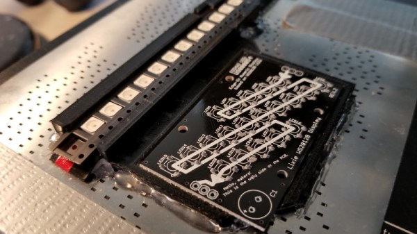
But if you have a very specific use case, namely a PCB that only has a relatively large single part that doesn’t need to be rotated, [Connor Nishijima] might have a solution for you. He bought a $150 USD Monoprice Mini, and with the addition of a few printed parts, was able to build a machine that drastically cuts down the time it takes for him to build his LED boards. Best of all the modification doesn’t involve any permanent changes to the printer, he can just pop off the vacuum attachment when he wants to print something.

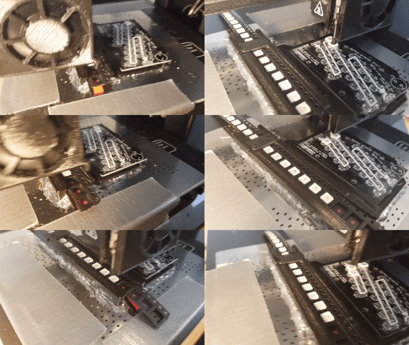
Beyond the 3D printed parts (which were made on the printer itself), the only thing you need to make the modification is the vacuum pump. [Connor] is using a hot air station that includes a vacuum pump for picking up SMD components, but he mentions that you’d probably better off just modifying an aquarium pump and using that. A printed holder snaps over the cooling fan of the Monoprice Mini to hold the vacuum pickup tool, and another printed piece holds the strip of LEDs and the PCB. It’s worth noting that the machine has no ability to control the vacuum pump, and doesn’t need to. The pickup tool is so weak that when the LED lands in the solder paste it sticks to the board well enough that the tool can’t lift it back off.

The real genius in this build comes from the manually written G-Code. You load it from the printer’s built in menu system as if it was a normal 3D print, and it instructs the printer to move the vacuum tool over the line of LEDs, pick one up, and drop it in place on the PCB. It then uses a small peg built into the vacuum tool holder to advance the line of LEDs before starting the cycle all over again. Incredibly, it does this whole complex dance 20 times for each PCB without ever having any kind of feedback or alignment check. It only works because [Connor] was willing to go through the trial and error of getting the calibration and G-Code down as close to perfect as can be expected for such a cheap machine.

This isn’t the first time we’ve seen the Monoprice Mini converted into something a bit more impressive than a cheapo 3D printer. Seems that for whatever the machine lacks in the printing department, it more than makes up for in hackability.

Continue reading “Monoprice Mini Converted To Pick And Place (Kinda)”

How—And Why—To Avoid Tolerance Stacking In Your Technical Drawings

If you want to have your part designs fabricated, you’re going to need to provide the manufacturer with a technical drawing. Yes, 3D printers and many modern machine tools rely on toolpaths created from 3D models. But, there is a good chance the manufacturer will be recreating the 3D model in their own system, instead of using the one you provided. Or, they may use traditional manual machining and not touch a 3D model at all. More importantly, the technical drawing gives them vital information on how closely they need to adhere to your dimensions in order for you to accept the parts.

On a technical drawing, the dimension that you want is called the nominal. But, no manufacturing is ever perfect, so you have to allow some wiggle room in what you’ll accept. That wiggle room is called tolerance. Maybe your part could be a little longer than specified and it wouldn’t affect the functionality. Maybe it could be a little shorter—or either. Specifying a tolerance is necessary, because it tells the manufacturer exactly how much wiggle room you’re giving them.

But, tolerances can introduce unforeseen consequences if you’re not careful. The wiggle room provided by tolerances is absolutely necessary, but if you don’t use them properly you can easily end up with unusable parts, even if the manufacturer followed your instructions to the letter. That usually happens because you have multiple tolerances being added together, which is called tolerance stacking.

Continue reading “How—And Why—To Avoid Tolerance Stacking In Your Technical Drawings”

Was The Self Driving Car Invented In The 1980s?

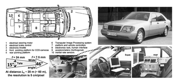
The news is full of self-driving cars and while there is some bad news, most of it is pretty positive. It seems a foregone conclusion that it is just a matter of time before calling for an Uber doesn’t involve another person. But according to a recent article, [Ernst Dickmanns] — a German aerospace engineer —  built three autonomous vehicles starting in 1986 and culminating with on-the-road demonstrations in 1994 for Daimler.

It is hard to imagine what had to take place to get a self-driving car in 1986. The article asserts that you need computer analysis of video at 10 frames a second minimum. In the 1980s doing a single frame in 10 minutes was considered an accomplishment. [Dickmanns’] vehicles borrowed tricks from how humans drive. They focused on a small area at any one moment and tried to ignore things that were not relevant.

Continue reading “Was The Self Driving Car Invented In The 1980s?”

Blinkbox: addressable LED testing tool

BlinkBox: Debugging Tool For Addressable LEDs

How often do you find yourself having to pause a project to make a test circuit or write some test code to find the source of a problem? Do enough variations of the same test and you’ll eventually make a dedicated test tool. That’s just what [Devon Bray] found himself doing.

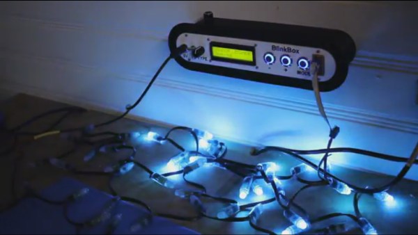
[Devon] does a lot of work with addressable LEDs of different types and after much experience, created the BlinkBox, a dedicated test tool for addressable LEDs. It supports multiple LED chipsets, you can give it a count of the LEDs you want to light up, and you can choose a test animation.  It even writes your settings to an EEPROM so you that don’t have to repeat yourself when you next turn it on.

He’s also done a very nice job packaging it all up, creating a 3D printed case, using backlit buttons for working in the dark, and even added a contrast knob for the LCD screen. Kudos to him for all the effort he’s put making this polished. Everything you need to duplicate it is available on his webpage, along with the schematic for the curious. Watch it in action, or just admire his handiwork in the video below.

Continue reading “BlinkBox: Debugging Tool For Addressable LEDs”