Over the years we’ve seen several attempts at adding Internet connectivity to the lowly wired doorbell. Generally, these projects aim to piggyback on the existing wiring, bells, and buttons rather than replace them entirely. Which invariably means at some point the AC wiring is going to need to interface with a DC microcontroller. This is often where things get interesting, as it seems everyone has a different idea on how best to bridge these two systems.
That’s the point where [Ben Brooks] found himself not so long ago. While researching the best way to tap into the 20 VAC pumping through his doorbells, he found a forum post where somebody was experimenting with optocouplers. As is unfortunately so often the case, the forum thread never really had a conclusion, and it wasn’t clear if the original poster ever figured it out.
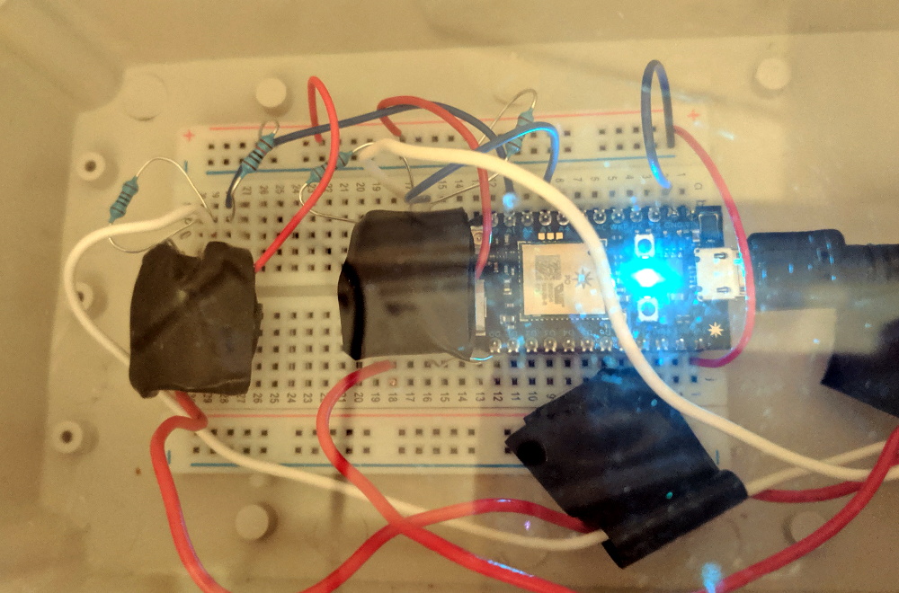
[Ben] liked the idea though, so he thought he would give it a shot. But before investing in real optocouplers, he created his own DIY versions to use as a proof of concept. He put a standard LED and photoresistor together with a bit of black tape, and connected the LED to the doorbell line with a resistor. Running the LED on 60 Hz AC meant it was flickering rapidly, but for the purposes of detecting if there was voltage on the line, it worked perfectly.
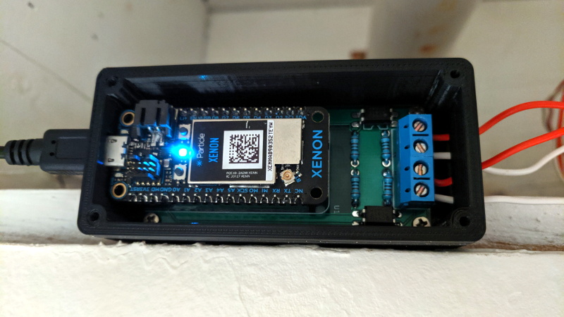
Wanting something slightly more professional for the final product, [Ben] eventually evolved his proof of concept to include a pair of 4N35s, a custom PCB, and a 3D printed enclosure. Powered by a Particle Xenon, the device uses IFTTT to fire off smartphone notifications and blink the lights in the house whenever somebody pushes the bell.
If you’re still wondering why it’s so tricky to connect a microcontroller up to your door bell, a quick look at some of the similar projects we’ve covered should give you a pretty good idea of how annoying these systems can be to modernize.


Apart from the challenge, why make this difficult? Instead of using signalling over 24VAC to trigger the microcontroller, connect the doorbell button direct to the microcontroller, throw in some code to trigger a relay to ring the actual bell (if you want to retain it) + your custom IOT function.
This requires too much re-wiring or bulky stuff inside the doorbell itself. An optocoupler, some resistors and an ESP8266 fit nicely into a doorbell housing (I did this with mine a few years ago). However, tapping the button and adding a relay, especially if you have multiple buttons or ringers becomes more complicated.
Two main reasons likely:
1) You still want the standard doorbell, which is designed to run off 24VAC, and is already wired up. They’re nice, loud, and very reliable, and provide important feedback to visitors that their button press has triggered the doorbell.
2) It’s probably wired in neatly. e.g. in the UK it’s normal for these to be wired in when the house is built; mine has a transformer in the consumer unit, and all the wires are neatly run behind the walls. It may not be trivial to reuse the existing wiring, and rerunning wires is a hassle.
Could have used an ESP32 for $5.00 to do the same thing.
Or ESP8266 for even less.
Also: use of an optocoupler is not very special and not even needed if you use the radio of the thing.
You can simply power it from the doorbel power supply.
Still had a brief look of what a “particle photon” is:
https://docs.particle.io/datasheets/wi-fi/photon-datasheet/
It’s an ARM Cortex M3 with a Broadcom Wifi Radio and small SMPS, which should have a regulated input of <= 5Vdc, and it costs around USD19.
I don't like Broadcom much, but still this may be interesting for lower power solutions then the ESPxx(xx).
Designing a decent power supply is a mayor hurdle for a lot of hobbyists.
If it had a SMPS to be powered from a Li-Ion cell or from an unregulated powersupply of upto 18 or 24V it would have had a big plus in usability, but as it is it just seems to be another non remarkable uC board.
Oops, mayour goofup.
The Particle Xenon has a slower ARM Cortex M-4F processor and a Nordic Radio chip.
https://docs.particle.io/xenon/
https://docs.particle.io/datasheets/mesh/xenon-datasheet/
It also seems better suited for battery applications compared to the Photon.
How would the ESP32 handle sensing the AC voltage of the doorbell circuit?
Point well made.
Input circuitry would be very similar to the same for interfacing an AC voltage to any low voltage uC.
Could also use a voltage divider, something like 10k / 1k would give you a 2 V signal. Drop in a diode to prevent it going negative and the signal at the uc would be pretty similar to what you get here—half wave rectified 60 Hz.
What you wouldn’t get is isolation (if that’s important to you which is not apparent here) and protection from surges and transients. If there were a surge the led/resistor would burn out but the rest would be ok.
If your µC has ESD proetction diodes at the input, you need just a single high value resistor. That was already suggested as mains voltage interface by Microchip for some of their PIC Microcontrollers.
You could also use this magical thing called a RELAY. Relay coil wired up with the existing doorbell. A press of the button closes the relay and rings the existing bell. Wire whatever micro controller you wish to use up to the contact points of the relay and treat it like any other push button input.
As for powering the microcontroller, a simple low voltage AC to DC converter with enough capacitance/supercap/battery on the output side to withstand a second or two long door bell button press, wired across the doorbell button should do. How do you think they make those light up door bell buttons that have been around for decades? a low power draw incandescent bulb or LED wired across the button. The current draw is small enough that it does not trigger the solenoid in the door bell sounder, till you press the button, short the bulb out of circuit and let the full flow of current though the solenoid.
A trickle charged battery/supercap is probably the best option, the trickle charging would not activate the existing door bell sounder solenoid, and the battery/supercap would be able to provide the large current rush required by a controller like an ESP being woken out of sleep mode then transmitting. The battery/supercap would be trickle charging the other 99.9999% of the time that the door bell button is not pressed.
I enjoyed this. I plan to do the same thing with an ESP8266 and figured that an optocoupler would be the smart thing to use. I have a bunch in my junk box. As far as choosing the controller, it is all about using whatever you are comfortable developing software for (unless your time is free).
My goal is to ring a bell in my shop when someone pushes the bell in the house. And I don’t want to run wire, so sending a message via the network would be smart — and allow many other features. Already have network in the shop.
This is overly complicated. Why not rectify the 12Vac present at the bell when it rings and a step down DC DC and directly power the ESP?
because the bell is not pressed long enough for the ESP to connect. You would need either a battery, power supply or some capacitor that is charged up quick enough when the switch is pressed.
Because a doorbell press lasts typically under a second. Whilst an ESP is an order of magnitude faster to boot than a RasPi, it can still easily take over a second to get though the bootloader, into your code, connect to wifi (this alone can take several seconds from a cold boot), and make the required HTTP/etc calls.
So you’d need to do something like put a super-cap in there, to keep the ESP going after the doorbell press has ended… adds more complexity.
“adds more complexity” as opposed to … adding an extra power supply, optocouplers, interconnection cables, boxes etc?
Yes.
You’re talking about a different kind of complexity, but using available and tested items is much easier than trying to build a circuit that will buffer enough power in a fraction of a second to run your circuit for several seconds. To speak of nothing else you’d have to be able to pull tens of Amps through your buck converter into the capacitors, so you’d have to vastly over-specify it compared to the always on version.
The “circuit that will buffer enough power in a fraction of a second” is called a capacitor. In that case a supercap would be the solution.
Even before the time when nearly everybody was climate-hysteric, I did not like to waste power unnecessarily, in that case standby power for an extra PSU.
When I wanted to “extend” my doorbell, I built a bridge rectifier with smoothing cap. Made about 10-12V DC and connected it to the transmitter of a wireless doorbell. I stuck this into the base of the handset. No extra battery, no extra PSU.
@Torro and @Dan there is ESP-NOW which is quite fast, but you need another ESP on the other end.
Still, the capacitor required to charge and maintain the ESP for 2-3 seconds will not be that big if you do the math and it can charge within a doorbell press.
Correct. My ESP NOW takes about 87ms to connect and send a message
That is sick! I need to look into that protocol someday…
https://arduinodiy.wordpress.com/2020/02/06/very-deep-sleep-and-energy-saving-on-esp8266-part-5-esp-now/
I used a cheapo 433mhz door sensor that I modded to remove the reed switch and use an optocoupler insead (less than $2) and fully integrated in domoticz now. I get a gif from my front door cam through pushover whenever someone’s ringing.
also, I did the same thing with my mailbox
Where comes the power, when you have galvanic isolation by an optocoupler? Hopefully not from a battery, when you have a free power supply at the doorbell.
For now it still comes from a battery, I expect it to last at least 2 years. I tought about a v2 using the power that comes from the door bell but it’s like 16V AC. Basically i should be able to remove the optocoupler and short the pads where the reed switch was and just rectify, and filter the AC, a resistor and a zener and just power the module when someone activates the doorbell
Nice job. I used a relay to interface with mine, as it made it very easy to interface with other devices. I used a double-pole relay, and it to both an off-the-shelf wireless doorbell button (with a battery powered slave which usually lives in the kitchen), and to an Arduino + ethernet shield which sends a message to a home automation server, and for speed, also broadcasts a UDP packet round the LAN for any listening devices (e.g. network slave arduinos elsewhere in the house) – you want very low latency for a doorbell, as delivery guys don’t wait long at all before giving up, and every second counts!
The home automation server sends a push message to my iphone & watch, and also triggers an ESP32-CAM to take a photo which it then pushes to my phone also (very handy to see if it’s a delivery guy, or the kids who can wait a second).
“off-the-shelf wireless doorbell button” – how is it powered by the relay? In my case I removed the 12V battery and bridged the button. The rectified doorbell AC power powers the transmitter, when the door button is pushed.
To those saying “Use a Relay” I’m not really sure why you are saying that is a more simple circuit. From the blog post, it’s a total of one optocoupler (at less than $1 USD) and 2 resistors per doorbell channel. He had a front and back door bell signal that goes to the actual doorbell box. So in one location, you can sense either doorbell for less than $2 plus whatever micro controller you want. Yes there is a small AC-DC power supply to power the Xenon, but the draw on that is very small.
Not cheap, but why not use a kinetic doorbell like https://www.amazon.co.uk/ERA-miChime-Battery-less-Wireless-Doorbell/dp/B01LZJSF8Z. And then use some device inside (probably that Raspberry Pi or similar that you already have anyway) to detect the signal and simultaneously ring a bell, send an SMS, WhatsApp, Messenger, email, Kodi popup, etc) that there’s someone at the door?