Behind The Scenes Of Folding@Home: How Do You Fight A Virus With Distributed Computing?

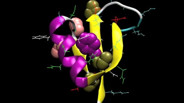
A great big Thank You to everyone who answered the call to participate in Folding@Home, helping to understand proteins interactions of SARS-CoV-2 virus that causes COVID-19. Some members of the FAH research team hosted an AMA (Ask Me Anything) session on Reddit to provide us with behind-the-scenes details. Unsurprisingly, the top two topics are “Why isn’t my computer doing anything?” and “What does this actually accomplish?”

The first is easier to answer. Thanks to people spreading the word — like the amazing growth of Team Hackaday — there has been a huge infusion of new participants. We could see this happening on the leader boards, but in this AMA we have numbers direct from the source. Before this month there were roughly thirty thousand regular contributors. Since then, several hundred thousands more started pitching in. This has overwhelmed their server infrastructure and resulted in what’s been termed a friendly-fire DDoS attack.

The most succinct information was posted by a folding support forum moderator.

Here’s a summary of current Folding@Home situation :
* We know about the work unit shortage
* It’s happening because of an approximately 20x increase in demand
* We are working on it and hope to have a solution very soon.
* Keep your machines running, they will eventually fold on their own.
* Every time we double our server resources, the number of Donors trying to help goes up by a factor of 4, outstripping whatever we do.

Why don’t they just buy more servers?

The answer can be found on Folding@Home donation FAQ. Most of their research grants have restrictions on how that funding is spent. These restrictions typically exclude capital equipment and infrastructure spending, meaning researchers can’t “just” buy more servers. Fortunately they are optimistic this recent fame has also attracted attention from enough donors with the right resources to help. As of this writing, their backend infrastructure has grown though not yet caught up to the flood. They’re still working on it, hang tight!

Computing hardware aside, there are human limitations on both input and output sides of this distributed supercomputer. Folding@Home need field experts to put together work units to be sent out to our computers, and such expertise is also required to review and interpret our submitted results. The good news is that our contribution has sped up their iteration cycle tremendously. Results that used to take weeks or months now return in days, informing where the next set of work units should investigate.

Continue reading “Behind The Scenes Of Folding@Home: How Do You Fight A Virus With Distributed Computing?”

3D Metal Printer Uses Welding Wire

If you’ve seen both a fused filament fabrication (FFF) printer and a wire welder, you may have noticed that they work on a similar basic principle. Feedstock is supplied in filament form — aka wire — and melted to deposit on the work piece in order to build up either welds in the case of the welder, or 3D objects in the case of the printer. Of course, there are a number of difficulties that prevent you from simply substituting metal wire for your thermoplastic filament. But, it turns out these difficulties can be overcome with some serious effort. [Dominik Meffert] has done exactly this with his wire 3D printer project.

Extruder cold end using a standard feeder roller

For his filament, [Dominik] chose standard welding wire, and has also experimented with stainless steel and flux-cored wires. Initially, he used a normal toothed gear as the mechanism in the stepper-driven cold end of his Bowden-tube extrusion mechanism, but found a standard wire feeder wheel from a welder worked better. This pinch-drive feeds the wire through a Bowden tube to the hot end.

In thermoplastic 3D printers, the material is melted in a chamber inside the hotend, then extruded through a nozzle to be deposited. Instead of trying to duplicate this arrangement for the metal wire, [Dominik] used a modified microwave oven transformer (MOT) to generate the low-voltage/high-amperage required to heat the wire restively. The heating is controlled through a phase-fired rectifier power controller that modulates the power on the input of the transformer. Conveniently, this controller is connected to the cooling fan output of the 3D printer board, allowing any standard slicer software to generate g-code for the metal printer.

To allow the wire to heat and melt, there must be a complete circuit from the transformer secondary. A standard welding nozzle matching the wire diameter is used as the electrode on the hot end, while a metal build plate serves as the other electrode. As you can imagine, getting the build plate — and the first layer — right is quite tricky, even more so than with plastic printers. In this case, added complications involve the fact that the printed object must maintain good electrical continuity with the plate, must not end up solidly welded down, and the fact that the 1450 °C molten steel tends to warp the plate.

Considering all the issues that have to be solved to make this all work, we are very impressed with [Dominik’s] progress so far! Similar issues were solved years ago for the case of thermoplastic printers by a group of highly-motivated experimenters, and it’s great to see a similar thing starting to happen with metal printing, especially using simple, readily-available materials.

This isn’t the only approach to DIY metal printing, though. We saw one that used electron beam melting (EBM) not too long ago.

Thanks to [Krzysztof] for the tip!

Fail Of The Week: In CAD, Remember To Model The Environment

What’s wrong with the above picture? Failure can be an excellent teacher, and [J. Peterson] reminds us all of this when he says to remember to model the environment when designing things in CAD. He contrasts a failure with a success to demonstrate what that means.

The failure was a stand for a screwdriver set, shown above. He modeled up a simple stand to hold a screwdriver handle and the bits in a nice, tight formation. He didn’t model any of parts, he just took some measurements and designed the holder. Everything fit just fine, but it had a major ergonomic problem: you can barely reach the handle because it is fenced in by the surrounding bits! Had he modeled all of the parts during the design phase, and not just the part he was making, this problem would have been immediately obvious during the design phase.

The contrasting success is an adapter he designed to mount an artistic glass marble to a lit display stand. The stand itself as well as the glass marble were modeled in CAD, then the adapter designed afterwards to fit them. With all of the involved objects modeled, he could be certain of how everything fit together and it worked the first time.

Now, to most people with a 3D printer of their own, discovering a part isn’t quite right is not a big (nor even a particularly expensive) problem to have, but that’s not the point. Waste and rework should be avoided if possible. To help do that, it can be good to remember to model the whole environment, not just the thing being made. Add it on to the pile of great design advice we’ve seen for designing things like enclosures and interfaces.