
From a guitar hacking point of view, the two major parts that are interesting to us are the pickups and the volume/tone control circuit that lets you adjust the sound while playing. Today, I’ll get into the latter part and take a close look at the components involved — potentiometers, switches, and a few other passive components — and show how they function, what alternative options we have, and how we can re-purpose them altogether.
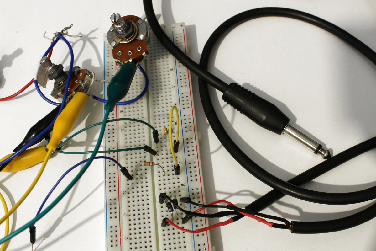
In that sense, it’s time to heat up the soldering iron, get out the screwdriver, and take off that pick guard / open up that back cover and continue our quest for new electric guitar sounds. And if the thought of that sounds uncomfortable, skip the soldering iron and grab some alligator clips and a breadboard. It may not be the ideal environment, but it’ll work.
When Music Meets Electronics
If you missed my last article, we covered the basics of electric guitars and the origin of their tone. To recap: steel strings vibrate over the magnetic field of a pickup, creating an electric signal that is shaped by all the pickup’s internal characteristics. From here, the signal is then routed through a volume and tone control circuit to the output jack, from where we can amplify and alter the sound however we want.
Before I start, I’d like to say a few words about guitar wiring diagrams you’ll come across on the internet, and the general state of electronics terminology within the guitar world. Since the average musician isn’t necessarily versed in electronics, actual schematics are rarely used to describe wiring, and the visual representation with life-like pictures, similar to a Fritzing breadboard view, are most common. This makes reconstructing and implementing the wiring itself a lot more straightforward in practice, but actually understanding the electronics behind it not so much.
Also, for some reason “nano” appears to be a taboo word, as capacitor values are usually stated in microfarad, and a 22 nF capacitor will commonly be referred to as a 0.022 uF, or simply “a point-oh-twenty-two” capacitor, and in worst case be written as “.022 mfd”. Although picofarad seems okay as well, so a 2.2 nF capacitor becomes 2200pF.
As a rule of thumb, capacitor values in guitar wiring are rarely above 100 nF or below 100 pF, so that should help decipher some more exotic nomenclature. With that out of the way, let’s get started.
Tone And Volume Control – Take Two
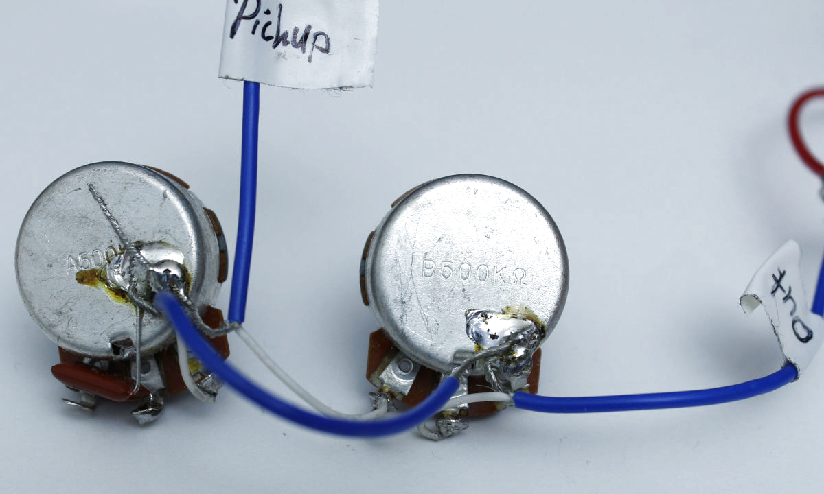
A typical volume control circuit is made up of a potentiometer with the pickup’s signal on one terminal, ground on the other terminal, and the output signal on its wiper. When it’s set to 10, the wiper has the least resistance and loudest volume, and at 0 the whole signal is discarded.
A typical tone control on the other hand is a low-pass filter made from another potentiometer and a capacitor. When set to 10, the pot is at maximum resistance and pretty much ignoring any impact from the capacitor. As the resistance is lowered, the capacitor starts affecting the tone by suppressing the highs, until it’s fully engaged at position 0. The higher the capacitor value, the more the high frequencies will be suppressed in total (or rather the resonant peak is shifted lower).
So much in theory, but in practice there’s a thing or two to consider here. For one, potentiometers won’t get fully down to 0 Ohm, but always have a little rest resistance, so the mere presence of a volume control is going to impact the output signal, albeit minuscule.
Modern Wiring Versus 50’s Setup
Also, the volume and tone control aren’t two isolated systems, but are interacting with each other. One result of that is a possible slight loss of highs when lowering the volume, depending how the wiring is actually set up.
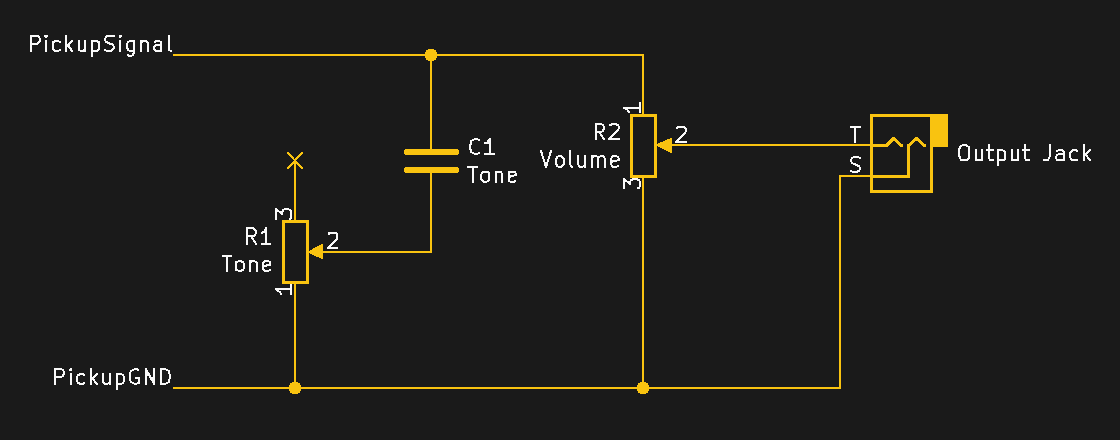
The Gibson Les Paul for example (and by extension other guitars with an individual tone and volume control for each pickup) can have a “modern wiring” or a “50s wiring” setup, where the tone control is connected to the volume control’s input and its wiper respectively.
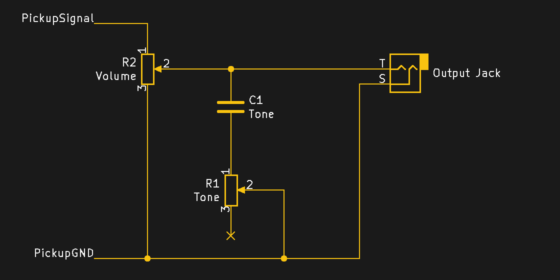
With the modern wiring, you will experience that slight loss of highs, while with the 50s wiring, the tone remains mostly unaffected when lowering the volume. However, as everything is connected, it’s not without consequences either. The tables have turned, and now the volume control will add some of the highs back when the tone control is engaged. If you rarely ever use the tone control, this probably won’t be an issue and the 50s wiring could be a perfect choice for you, but if you rely on that dark muddiness of a low tone control, you probably won’t be all too happy with it.
Treble Bleed
An alternative to countering the loss of highs without affecting the tone control behavior too much is the so-called treble bleed circuit that essentially adds a high-pass filter to the volume pot. In its simplest form, it’s just a capacitor parallel to the input terminal and wiper, which some manufacturers even use in some of their model’s stock wiring. Ibanez for example uses here 330 pF, G&L 200 pF, and PRS goes down to 180 pF. Going above 1 nF might however run the risk of getting a quite harsh, overly bright tone without much lows left at all. For some more options, alternate versions exist that use a resistor either in parallel or series.
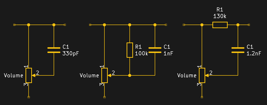
The values in the schematic above are more a starting point and might require some experimentation to find a perfect match. The actual behavior of the controls, including the treble bleed behavior, also depends on what potentiometer is used, or rather what kind of taper.
Taper? I Hardly Even Know ‘er
Potentiometers that are commonly found in the guitar’s controls come with different types of tapers, i.e. the part that actually causes the resistance in them. The two most common types are linear and logarithmic (or audio) tapers, followed by an occasional occurrence of a reverse logarithmic taper. As the name suggests, their difference is how the resistance value changes based on the wiper position, so either linear or in an exponentially increasing (or decreasing if reverse logarithmic) way.
In terms of volume control, a linear potentiometer set to 5 will (ideally) have half the output signal level, but considering the human ear’s non-linear volume perception, it won’t equal half the volume. For that reason, it’s often recommended to use logarithmic tapers for the volume control to match up that behavior (hence their alternative “audio taper” name), but it also begs the question: does a guitar volume really have to be at half its volume when set to 5?
Well, to answer that question, it mainly depends on how you’re using your volume pot and how you want it to behave. Some might stay within the 10-6 range and prefer distinct changes with little movement, others idle on 6 and turn it up for a casual boost here and there. Some crank up the amp to max and use the volume knob like on an old TV or radio, and others just marvel at the perfect dust gradient forming on it. So to no surprise, opinions on whether a linear or logarithmic tapers are the right choice for volume controls are divided, and manufacturers haven’t always made up their mind either, although that might very well have economic reasons.
It’s similar with the tone control’s taper choice, though the majority seems to be on the logarithmic side with that one, as it actually results in a more consistent overall sweep. But tone controls are also a bit of a different story, as their lower settings are still practical, and even all the way down at 0 is a valid option and used regularly in some styles, unlike the volume control, which is simply silent at that point, and anything below 3 might be of limited use, too. Still, that doesn’t mean a linear taper couldn’t be the right choice for you. Its abrupt descent into darkness compared to a logarithmic taper might give you just what you want for some tone pot based effects.
After all, the point of all this is to modify the guitar’s tonal behavior, so let’s not limit ourselves to whatever seems to be the normal way of doing things with the controls. And while the taper behavior is a fixed character of the potentiometer itself, it’s still only a resistor. Does your tone pot set to 0 just end up dull and muddy? Maybe try an additional resistor in series to keep it from going all the way down to zero Ohm. The sound of a 500 kOhm pot is too bright for your taste, but 250 kOhm is just missing something clarity? Maybe a 2.2 MOhm in parallel to that 500 kOhm can sweeten it up. Well, try and see what happens.
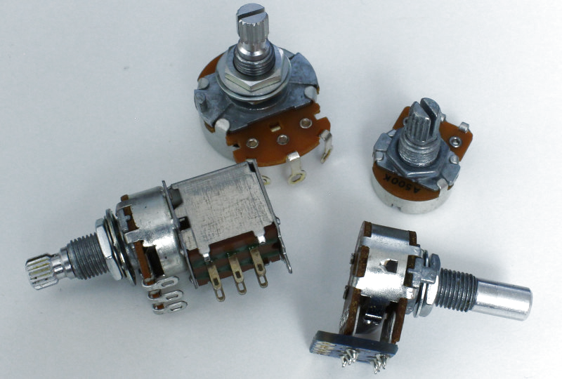
Doubling Down On Potentiometers: Blend, Stacked, Dual Gang
Okay, so potentiometers have different tapers and of course come in different values. Some might have a unique, customized taper behavior or are no-load pots that circumvent the problem of “even at zero there’s still a slight leftover resistance” by completely disengaging the taper in that position. Opinions are again divided on those though, as getting a raw unadulterated signal from the pickups is a nice thing to have, but also adds a tad of unnatural response once the taper gets back into the system.
But apart from physical characteristics like their overall size and shaft construction, there’s not much else to a potentiometer. So how about putting two of them together into a single housing? Well, then we can either end up with a blend pot or a stacked (or dual gang) potentiometer. Both are essentially two pots stacked on top of each other, with one single shaft turning two independent tapers. The individual potentiometers are usually accessible on their own, and therefore have separate connectors for each of them.
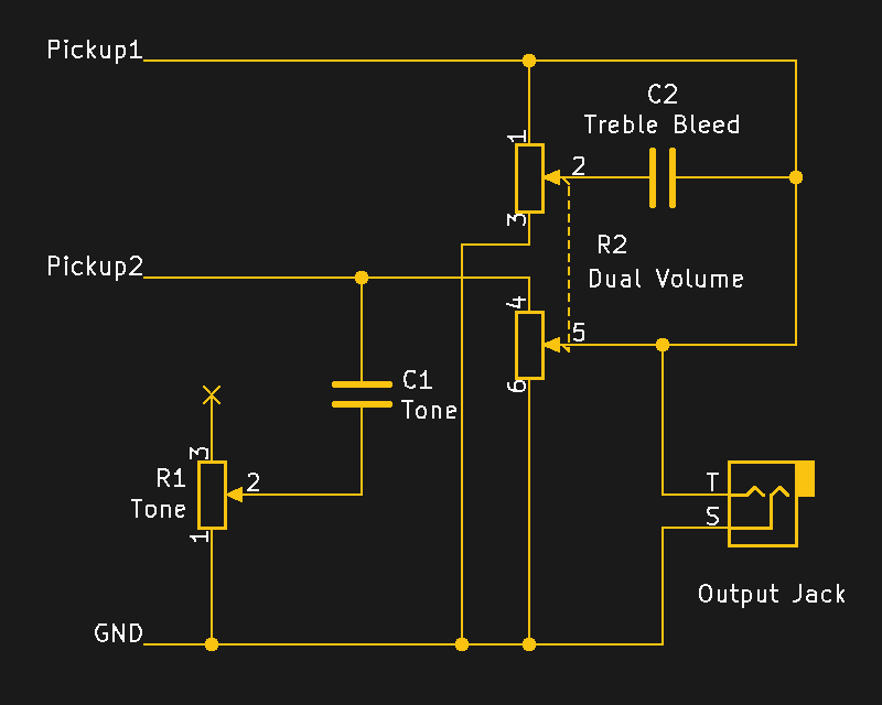
Let’s take a simple single-volume, single-tone control wiring on a guitar with two pickups as an example. Maybe the bright bridge pickup could use an occasional spin on the tone pot, while the neck pickup is just perfect as-is, and you don’t like the muddy sound of a low-pass filter on a neck anyway. Using a dual-gang potentiometer with two identical potentiometers (e.g. linear 500 kOhm) could let you connect each pickup to its own individual volume pot, and the tone control is only connected to the bridge’s. Maybe add a treble bleed circuit that only affects the neck pickup while you’re at it.
Or maybe one of those pickups is a single coil while the other is a humbucker, a dual gang potentiometer with 250 kOhm and 500 kOhm respectively could handle their differences in a single control.
Fender for example has some HSS Stratocasters (i.e. a Stratocaster with a humbucker in the bridge and the usual two single coils in the middle and neck) with the latter arrangement, which additionally separates the Strat’s two tone controls for single coils and humbuckers. Since the potentiometers use a single shaft, it won’t make any difference in actually controlling it.
Unless that’s something you’d want, in which case, you can have that as well with a concentric potentiometer. It’s still two individual, stacked-together to fit in the space of a single potentiometer, but this time the shaft has an inner and outer log for turning each one separately.
Say you want that Gibsonesque way of separate tone and volume control for each pickup in a guitar that wasn’t built for that. Sure, you could get out the power tools, but that’s definitely not everyone’s cup of tea — and maybe a bit more difficult if we think of a Telecaster with its metal plate and quite limited control cavity space. Concentric potentiometers to the rescue! Okay, you’ll need a special knob to handle the two separate shafts, but you can fit both in the space of a single potentiometer without any other drastic modifications. The original Fender Jazz Bass actually had such a configuration before they switched to the nowadays common bass wiring of two individual volume controls and single main tone control. Which kinda brings us to blend pots.
Blend pots are a special kind of “two pots in one housing”, and are the ones you find as balance control in an audio amplifier, usually with that little notch in the center position. In theory, you could use them to blend two pickups together instead of having two separate volume controls for them. However, at least for passive controls, that’s more a nice sounding idea than anything of much practical value. In reality, you might neither get a pure bridge nor neck pickup sound as the other one is always slightly bleeding into the signal, and worse, you might end up with a significant volume drop in the center position. (Though there is also the chance I simply botched my own wiring, or should have used a different blend pot.)
Note that there’s another “blend control potentiometer” wiring in existence, which is also about blending pickups together, but stems from the very early days of the Telecaster and has nothing to do with the blend potentiometers just mentioned. This one’s actually cool though, so I’ll come back to it in a bit.
Switching It Up
An interesting variation of a regular potentiometer is the push-pull pot that has an additional DPDT switch mounted to it. The switch itself is completely separated from the potentiometer, but the switching mechanism is activated by pulling out and pushing in the potentiometer’s shaft. A similar variety is a kill switch pot that has a momentary SPST push switch integrated that is meant to temporarily kill the signal by shorting it to ground to generate a unique effect (which is excessively used for example by Buckethead).
Switches are an incredibly valuable asset when hacking a guitar, as they allow us to enable and disable individual modifications on demand — increasing the guitar’s total tonal variety compared to a fixed wiring — and open up even more options where a potentiometer alone wouldn’t get us far. Like, why choose whether to use a 22 nF or 47 nF capacitor for that tone control if you could just have both and toggle between either one of them as you feel like. Or let’s say you found this one amazing sweet spot on the tone pot, instead of tediously trying to find it again every time, use a switch to bypass the tone pot with a fixed resistor of the exact value you’re looking for. Why not bypass the controls altogether and get that raw pickup signal? Not to mention what we can do with the pickups themselves here, but let’s not get ahead of ourselves.
The great thing about using push-pull pots here is that you don’t need to drill any extra holes into the guitar body to add a switch, but can just replace one of the existing potentiometers with it and keep all the original controls as-is. And if you’re willing to sacrifice the tone pot completely, you could take this even further with a rotary switch of matching dimensions and instead of toggling between two options, select one from as many options as the biggest switch that fits in the control cavity offers. B.B. King for example had five separate filters (along with a sixth bypass option) selectable on his Gibson ES-355, which Gibson is nowadays marketing as Varitone circuit.
Of course, if you don’t mind doing some heavier modifications to the guitar body, standard mini toggle switches are always a solution if you’re otherwise running out of switching alternatives. On the other hand, there’s one other switch that you might not think of as option here: the pickup selector switch. Now, yes, removing the option to activate different pickup combinations might seem a bit counter-intuitive on the subject of expanding a guitar’s tone, but let me get back to that Telecaster blend control I mentioned a bit earlier for that.
Pots Beyond Tone And Volume Control
Back in 1950, Fender released their very first electric guitar, the Esquire, featuring a single bridge pickup. Despite having just that one pickup, it was still equipped with a 3-way selector switch. So what did that switch do then, as it’s clearly not toggling between pickups? Well, it essentially selected the tone control behavior.
While the volume control was always active, the tone control was either active, completely bypassed, or replaced by a fixed low-pass filter that produced a muffled bassy sound. Note that the double bass was pretty much the only string instrument available for playing bass lines at that time, which is a big, chunky piece of furniture that can’t be just plugged into an amplifier. So darkening the tone on the guitar to its extreme was a good alternative until the electric bass became a thing a year later.
Soon after the Esquire was introduced, the initial Telecaster was released (titled Broadcaster at the time), looking just like the Esquire, except it had a neck pickup added. At that point, the 3-way switch could have been changed to be a pickup selector as we know it today, but Leo Fender wanted to keep that muffled bass option around, so that switch position remained as-is (except it used the warmer, darker-by-nature neck pickup now). However, the other two positions now selected between either the neck pickup with the tone control being a regular tone control, or the bridge pickup with — here we go — the tone control turned into the aforementioned blend control. What it did was gradually blend the neck pickup signal into the bridge pickup signal, transitioning from bridge-only at 0 to “middle position” at 10, as well as anything in between, creating some unique combinations.
Telecasters today rarely look back at that blend control — most players never cared much for that muffled bass tone anyway, so with the 3-way switch eventually turned into a regular pickup selector, there was no practical need for the blend control anymore. However, Stratocasters may occasionally use it, which makes sense. If we recall, a Stratocaster has three single coils, a 5-way switch that won’t allow all possible combinations, and a somewhat weird tone control setup with separate tone pots for two pickups, and none for the third. Changing one tone knob to control the overall tone, and turning the other into a blend control will get you that otherwise impossible bridge-neck or all-three-of-them combination (well, unless you use a switch, of course) along with a nice blend of partially engaged pickups.
Again, I’ll go deeper into pickup wiring next time, but as a sneak peek in the meantime, an interesting take on the same concept is having a humbucker that exposes both coils’ wires (which allows you to use it as two separate single coil pickups) and apply the blend control on those two coils. So instead of blending two separate pickups together, you can blend a single pickup from being a single coil to becoming a full humbucker. In fact, the Fender Jaguar HH (i.e. double humbucker) model is stock-equipped with such a wiring, and is anyway an interesting instrument when it comes to wiring.
We’ve Only Just Begun
So as this shows, potentiometers can be used for more than just controlling volume and tone, pickup selector switches can be used for more than selecting pickups, and consequently, there are alternative options to select a pickup. To add to this, how about using some mini toggle switches to enable and disable pickups individually (like Brian May’s Red Special for example) and turn that pickup selector switch into a Varitone-style filter selector?
While we’re at it, why not ditch low-pass filters altogether and replace them with high-pass filters? I already mentioned the treble bleed circuit as one option for that, but the regular tone control itself could just have the capacitor in parallel instead of the usual series wiring. So instead of suppressing the highs when turning that tone knob, it’s the lows that will be cut off now. If you have two tone control potentiometers (or one you can otherwise spare), why not have both options at once? Or how about throwing in an inductor and cut out the middles with some band-stop filter? As I mentioned last time, math formulas won’t get you far here, so you might just run some experiments with throwing things (to an extend) randomly together and see what happens.
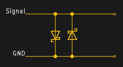
And to expand on that even further: diodes! Wiring two of them in opposite direction between the signal and ground can add some nice little crunch to your sound by capping off the signal beyond their forward voltage. Of course, this won’t replace actual effect pedals, it’s still only passive electronics and modifications like this will make you lose some signal, but it’s still a fun thing one can do. Keep in mind though that the average pickup produces only a few hundred millivolts of signal, so a regular silicon diode’s forward voltage drop is usually too high, and you’ll have more success with either a Germanium or Schottky diode. For more information, and how to to go full rectifier mode with it (and not spend $30+ for the commercial version), check out Joe Beau’s guide on the subject.
Well, that covers the potentiometers we find in guitars in all their glory and variety, and how we can use them along with switches to modify the volume and tone controls. This topic is certainly not completely exhausted, but I hope this gave you some new ideas on experimenting with the wiring of an electric guitar, and most of all, gets you thinking outside the box entirely when it comes to that. As long as you keep external power supplies out of this, and maybe stay away from directly soldering on the pickup coils, you and your guitar will probably be fine.
Next time we’ll take that same spirit back to the pickups and forget everything I said about “humbuckers are two single coils connected in series” and “the middle switch position puts two pickups together in parallel”.


the hackaday logo guitar is excellent :)
Coming Soon to Tindie!
(j/k)
It’s my lucky day. I’m building my first guitar. I decided on building my own wiring from scratch because I had most of the parts, and I’m more of an electronics hobbyist than a woodworker. (I cheated and bought a “husk” for a Epiphone Les Paul Studio, with set neck)
One resource I found very helpful was Seymour Duncan’s website for wiring. They have many dozens of variations on circuits with non-standard but easy to read wiring diagrams. https://www.seymourduncan.com/resources/pickup/wiring-diagrams
And Stewmac has a very basic guide on some of the terminology that ends up in the world of guitar wiring. It helps in finding the right keywords on ebay and aliexpress for components, and to get a sense of how the push-pull pots work (not something I’ve encountered before this). https://www.stewmac.com/video-and-ideas/online-resources/learn-about-guitar-pickups-and-electronics-and-wiring/understanding-guitar-wiring.html
No shame in taking a shortcut I’d say. Sure, a guitar you carved by hand from a tree that grew in the backyard of your childhood home has definitely a more special meaning than one built from a kit, but you also mind a lot less to go wild with powertools on the kit guitar. Both have their place I guess (I have yet to carve one from scratch myself – probably going with an old sauna bench here)
But yes, the Seymour Duncan website is an awesome resource, and I’ll make sure to refer to it in the next part.
Good luck on your wiring adventure :)
I could say it again. It’s time the electric guitar have more in it than 2 pots a cap and a switch. Lithium power with on board digital processing, power amp, and speaker. I go all the way. We aren’t all playing like Charlie Christian only. A radio or phonograph had a “tone” control now we have 10 band EQ and more. The guitar pickup has a rather high impedance compared to today’s audio connections, which makes it easy to do these old school tricks. Meg-ohm pots are kinda rare now, even 500K aren’t used in modern electronics.
A Gibson Les Paul set up for high-gain(metal, hard rock) has 4 pots, 2 caps, and active pickups with transistors/op-amps and a 9V battery. It sends a very hot signal out to the amplifier, were the most wonderful distortion happens.
I think a multi-band EQ is not necessary for most styles of music if you have a base/mid/high tone control with a movable center on the mid. That is easy to operate to find the sound you want. Most EQs are a bit too subtle because of how a band-pass filter is usually implemented, tends to be good for clean tones but gets in the way of making something with some “bite” to it.
You can swap in 250K or odd-ball custom sizes if you’re unhappy with 500K. But I will admit that guitar circuits are very old fashioned. The reason is the output is not from the leg of a transistor (BJT, MOSFET, etc). And that moderately high impedance output of a typical guitar plays a lot with whatever you plug it into. guitar+cable+amp is a circuit onto itself when it comes to analysis. Although once you plug yourself into a pedal, the boost section in the pedal turns it into that nice modern signal. Integrating a boost pedal into your guitar would be very simple. It would get in your way if you’re searching for a specific vintage tone. But you could find the setup very convenient for gigging. Then you can plug into equipment not under your control at random venues. (or bring a pedal board and not modify your nice guitar – same thing electrically)
We do have that stuff for our instruments, just not built into the guitar.
I guess VOX guitars go roughly in that direction.
Point of history:
“Also, for some reason “nano” appears to be a taboo word, as capacitor values are usually stated in microfarad, and a 22 nF capacitor will commonly be referred to as a 0.022 uF, or simply “a point-oh-twenty-two” capacitor, and in worst case be written as “.022 mfd”. Although picofarad seems okay as well, so a 2.2 nF capacitor becomes 2200pF.”
When I was in uni, most of my profs were still learning to say “pico” rather than micro-micro when speaking of capacitance.
It wasn’t until the 1990’s that nano- really tool hold in the US for cap values, and even in the mid 2000’s I would get components (usually ceramic disc caps) marked using the old 0.1 for 100nF, rather then 104 (for 10 followed by four more zeroes picofarads), with the catalog values being listed likewise.
Essentially, the initial statement says that the guitar world has et to transcend the 1980’s, which is no surprise.
Interesting, thanks! I didn’t get in contact with electronics until the very late 90s, so I never saw the old values outside the guitar world. But makes sense now, yes.
i noticed my crunch box uses a pair of leds instead of schottky diodes. i presume this gives you some semiconductor options as different led colors use different semiconductors. my schematic called for red, but i wonder what would happen if i put some blue ones in there.
My understanding is that tone-wise, it’s all about the voltage thresholds — how hot the incoming signal needs to be to drive them into clipping. Traditional red LEDs are around 1.7v, compared to a silicon diode’s 0.7v or a germanium’s 0.3v. Since blue LEDs can range between 3.2v and 4.5v, probably nothing good would come of subbing them in, unless you’ve got a serious preamp ahead of it (or, I suppose, if you’re wanting to use it on ±5v Eurorack levels).
I think pretty much what [Taper Wickel] said, and depending on the signal level you have in the box, the crunch effect will either set in a lot later (gain knob won’t have any effect in the lower area I guess) or simply not at all. Other way around, using a regular diode (or Schottky or germanium) will clip probably too early and is at full crunch with low gain settings (I’m not familiar with the box in practice though)
PRS = Paul Reed Smith. I hope you’re going to talk about installing a phase switch, which is probably the easiest modification you could do.
Excellent as always! Really look forward to these guitar posts. There’s a whole lot of woo and cargo culting on message boards; it’s nice to see decent, detailed explanations that don’t completely disregard art and nuance.