A solderless breadboard is a place where ideas go to become real for the first time. Usually, this is a somewhat messy affair, with random jumpers flying all about the place, connecting components that can be quickly swapped to zero in on the right values, or to quickly change the circuit topology. Breadboards aren’t the place to make circuit artwork.
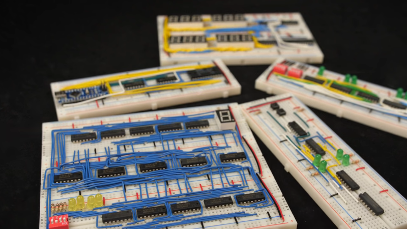
 That is, however, not always the case, and we’ve seen more than a few examples from [Ben Eater] on breadboarding that approaches the circuit sculpture level of craftsmanship. And like any good craftsman, [Ben] has shared some of his breadboarding tips and tricks in a new video. Starting with a simple 555 blinkenlight project that’s wired up in the traditional anything-goes fashion, [Ben] walks us through his process for making a more presentation-worthy version.
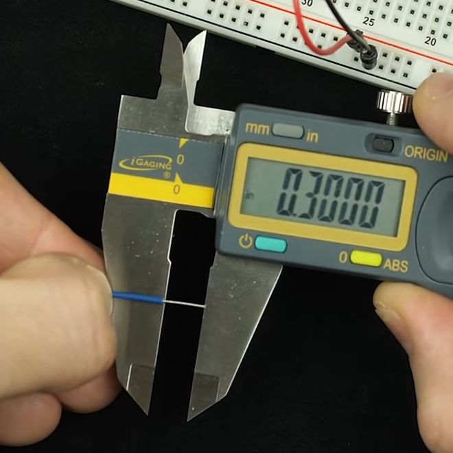
His tools are high-quality but simple, with the wire strippers being the most crucial to good results. Surprisingly, [Ben] relies most heavily on the simple “scissors-style” strippers for their versatility, rather than the complicated semi-automatic tools. We found that to be the biggest take-home from the video, as well as the results of practice. [Ben] has done tons of this type of breadboarding before, which means when he “eyeballs” stripping 0.3 inches of insulation, he can do it down to a ten-thousandth precision.
Granted, there’s not much new here, but watching this video is a little like watching [Bob Ross] paint — relaxing and strangely compelling at the same time. You can get more of the same with pretty much any of his videos that we’ve covered, like this 6502 breadboard computer build. We’ve also seen [Eater]-inspired builds that are pretty impressive, like this full-8-bit breadboard computer.


While [Ben]’s prototyping skills are noteworthy, his teaching skills are legendary. If you want to know EXACTLY how a simple microprocessor works, to the point where you could design one yourself, his series on an 8-bit computer build (not the 6502 series, but the TTL logic one) can’t be beat. Be prepared to pause the video, because Ben DOES NOT REPEAT himself. Which to me is a breath of fresh air. Sometime in the past, somebody declared that if you want to teach something, you must do so three times. Which is utterly maddening to me. If you thought I didn’t understand what you said the first two times, what makes you think it will sink in on the third telling? At best I understood it the first time, so you wasted 2/3 of my time, and at worst I still don’t understand it, and wasted 3x as much time. But like I said, Ben does not do this; he expects that his audience is capable of paying attention. His other series, on digital communications, is also a must-see, even if you think you already know everything about it.
Listen to him closely. He actually does follow the “tell it three times” method – he just does it unobtrusively and correctly.
Each section starts with a short summary of what he’s going to discuss, followed by the “meat” if the subject, followed by a quick review that often doubles as the transition to the next topic.
The old military briefing …
– tell them what you are going to say
– say it
– tell them what you just said!
As used in schools in the U.K.
finished circuit looks awesome! but playing the devils advocate, don’t wires parallel to each other introduce crosstalk, longer wires have longer propagation delay, and last but not least more wire is consumed…
Yes, but if you’re worried about such things then it’s time to move on from breadboards anyway. As for the wire consumption, he’s talking about building semi-permanent things, where wires laying flush on the board are kind of a necessity. And lastly, the speed of light is about one foot per nanosecond (less in copper), so signal speeds at which this matters are outside of the realm of breadboard capabilities anyway.
How else else does a hacker have fun ‘cept to post comments that are ridiculous[mine]…it would be great for sure if breadboard was cheaper than perfboard. I have noticed on a few motherboards traces that are zig-zaged, I presume thats to add a picoseconds delay
A lot of high-speed signals now run over differential pairs where both traces must be the same length; and if you have a bunch of such signals you may want the same length for *all* of them. Many “zigzag” layouts are for this purpose.
My top tip for breadboard prototyping: electrical contact cleaner spray. That weird fault could be corrosion on your breadboard contacts.
My frequent bugbear is not realising there’s still a bit of gloopy tape reel glue on the end of a resistor or diode and shoving it in there, derp. Need to lash up some kind of cammed roller thing that wets itself with IPA and pulls tight to wipe the ends of components you stick into it. Such that it’s not something else you have to pick up and put down, so handsfree on the bench, becoming part of the motion of inserting the component, pick up component, dab it in that, put it in the board. Thinking it would look a bit like those old cigarette rolling machines. (Small enough diameter rollers that you can wipe a DIP chip in it) Loop of “Jeye” cloth on each roller maybe?? Not sure whether to have it wick the IPA or have a spritzer, because sticking even a small wick in IPA I think you might lose a bottle full every couple of hours to evaporation. Hmmmm
I avoid this by clipping right behind the tape instead of peeling out, at least for resistors and diodes, partly because the long waving legs are a liability and losing 1/4″ off a resistor leg shouldn’t be a make-or-break difference in bboarding
True, that’s what I will do when I notice it’s gloopy. However, there’s still oxidation, and things like random scraps of old electrical tape falling among your components and glooping them in random places along the lead. Antistatic foam turns to tar when you’re not looking too. Less problem for soldering, add more flux.
I use a pencil eraser for soft metals like gold contacts on a computer memory SIMM. For harder metals like tin or copper I use the ink side of a pencil/pen eraser.
Something I have begun to experiment with is soldering 0805 SMT resistors onto a pair of header pins. The resistor just almost fits, at a slight angle. It takes up a lot less space on the breadboard, and (if you were paying attention when you put it together), the value is visible, without confusing less-than-perfect color vision. I acquired a large (for SMD-scale values of “large”) quantity of pick-n-place reject parts (from monthly vacuum clean-outs), along with a few reels, so I have a nice assortment of values to work with.
It still brings up the question of how much do header pins bend out the breadboard contacts, but at least they’re gold-plated!
I’ve had a bad experience with plugging header pins into solderless BBs. Because they are substantially larger than most component leads, they tend to “spring” the contacts, making them useless for leaded components.
Breadboarding is for breadboarding, not a finished project. So why waste time making things look good?
I made jumpers as I needed them. Some bare for jumping adjacent pins, then varying length as needed. When I was finished, the jumpers went into a parts drawer, ready to be reused. Once I had a collection, I’d try to use small when needed, but I never fussed much. Eventually I’d need to cut some new jumpers, the copper wire eventually wearing out.
All the jumpers came from leftover telephone cabling, which wasn’t a frequent sight in public garbage cans, but it appeared enough times to be reliable.
Some padts didn’t fit the breadboard, either the leads too big, or spaced wrong. So I just soldered leads to them as needed. Some parts, like switches from and pots, I dedicated to breadboarding, so the wires remained in between breadboarding.
I can barely remember when those white breadboards were a new thing.
” leftover telephone cabling”
Heh, I renewed my supply the other month when we had a city wide, “put stuff out to curb to get rid of it that other ppl might want” type of day.
RW that’s a thing? Who organises it and how is it publicised?
We could do with that sort of thing where I live.
Relatively new to this area of Ontario, mostly termed a “Curbside Giveaway” day here. I understand it’s a thing in parts of Australia also, and has been known in Cali, but not sure what they call it there…
Here seems to be the local municipalities organising, such as …
https://www.newmarket.ca/LivingHere/Pages/Waste,%20Recycling%20and%20Organics/Curbside-Giveaway-Days.aspx
or
http://www.vaughan.ca/services/residential/solid_waste_management/Pages/Curbside-Giveaway.aspx
But everything called off now due to covid lockdowns, ours went off in October before restrictions tightened again.
> Breadboarding is for breadboarding, not a finished project. So why waste time making things look good?
because some projects might require breadboarding a system for days/weeks, and you’ve got to deal with your rats nest that entire time.
certainly folks having to follow ben’s videos to put one of these together might require more than a lazy afternoon to get it all taken care of, and could use all the help they can get keeping the project straight in their minds.
Also, in [Ben]’s case, he often removes components from a breadboard used in a previous video, to add functionality. In this sense, he doesn’t HAVE any “finished” projects. Having clean wiring means wires don’t accidentally get snagged and removed, and if a wire DOES pull out, you can figure out pretty easily where it came from.
I wondered what that more complex breadboard in last 3rd of video was, looked interesting, it’s his 6502 system https://eater.net/6502 Which might be enough similar to the “Mystery Meat” board on my .io as to be able to follow along his bring up and programming to be able to do something with it.
Once worked at a small DoD test and eval facility, where the Chief Engineer (MS mech eng and MS math) insisted that breadboards were just fine for one-time tests on tactical vehicles. The war between engineering management and the engineering lab folk (EEs and techs) was bloody and lasted for almost a year until the next Director (an 0-5 mil officer), also having an engineering degree, ‘mediated’ the war and told the Chief Engineer to shut up and sit down. My last year at that place was significantly more enjoyable.
Sounds technically correct, in that it would work that one time, before you engaged drive and went off down the road. :-D
now where did that diode bounce off to….?
He can film it ten times and pick the video where he got 0.03000. Come on. At some point the look-at-me stuff is distracting and adds no value. Sorry to be that guy.
Dan says he got it down to a ten-thousandth, but Ben makes no such claim. He actually says it’s “a little long” if you’re paying attention.
He just has the calipers dialed in to 0.3000 and set there (usually they have a thumb screw to hold them on a set value). He put the wire up to them to compare and said it was “maybe a little longer; that’s fine,” watch again at about 6:00.
This feels a bit old school. But first, I have to admire the neatness and obvious care that he put into this. And, they truly are great learning tools.
Old school because with cheap fast turn around on PCBs, you can have a much more reliable project in fairly short order – Covid-19 postal delays not withstanding.
They do have their place, though. I use SBBs to try out simple things, evaluate a given part or test an idea but complete (and/or complex) assemblies are just better left to printed boards. While it is tempting to make a full system breadboard work because it is pretty quick, extended testing can be maddening. In the 70s and 80s people built complex prototypes boards with wirewrap. Much better than SBBs for reliability but even back then they tossed it away to go straight to PCBs. The costs were much higher than today for a quick turn, proto PCB run but worth it when factoring in debug time.
Going straight to PCBs is fine and all for you people who seem to know what you’re doing, but I majored in CS and thus anytime I design something without testing my assumptions on a breadboard I end up waiting two weeks for nice clean circuit boards that have to go straight in the trash because I forgot how electricity works. :P
i try to design my boards to allow for some mistakes. don’t make traces smaller than necessary, increase the gaps, add test points, bring things out to 0.100″ headers, route the traces assuming you might have to cut them, etc. Helps out quite a bit.
It takes a heck of a lot of time to jockey through some PCB design program, find the right component footprints etc. and when it turns around you end up doing a whoole bunch of work. Then you’ve got the board, you still need to solder it together, and then… what? did you expect your first iteration to actually work? Oh, but it’s fixed so you have to start over….
In case anyone was curious, I’m pretty sure the reason he’s using the 24 gauge setting on his strippers is because of differences in diameters between solid and stranded wire. Typically with small gauge wires like this, the difference is equivalent to about 2 gauge sizes. So a 24 gauge stranded wire is approximately the same diameter as a 22 gauge solid wire.