GPS technology is a marvel of the modern world. Not only can we reliably locate positions on the planet with remarkable accuracy and relatively inexpensive hardware, but plenty of non-location-based features of the technology are available for other uses as well. GPS can be used for things like time servers, since the satellites require precise timing in order to triangulate a position, and as a result they can also be used for things like this incredibly accurate frequency reference.
This project is what’s known as a GPSDO, or GPS-disciplined oscillator. Typically they use a normal oscillator, like a crystal, and improve its accuracy by pairing it with the timing signal from a GPS satellite. This one is a standalone model built by [Szabolcs Szigeti] who based the build around an STM32 board. The goal of the project was purely educational, as GPSDOs of various types are widely available, but [Szabolcs] was able to build exactly what he wanted into this one including a custom power supply, simple standalone UI, and no distribution amplifier.
The build goes into a good bit of detail on the design and operation of the device, and all of the PCB schematics and source code are available on the projects GitHub page if you want to build your own. There are plenty of other projects out there that make use of GPS-based time for its high accuracy, too, like this one which ties a GPS time standard directly to a Raspberry Pi.


I was expecting he built a GPSDO. The 2nd paragraph implied that it is built around the STM32, it is not. The GPSDO is already built and he uses TruePosition board and put an enclosure on it.
Disappointing. He did not build a GPSDO. He took an existing GSPDO and built a case, power supply, and user interface for it. Which is potentially interesting, but it’s not what the article implied.
What is wrong with the hole for the LCD? I’m curious to know what could be improved (considering you couldn’t even be bothered to say) but pure laziness? Really? How are you going to be rude without at least showing us the one you made..
He could not be as rude, but yes, the hole is imprecisely cut, and also the hole is too large and the LCD frame is sticking out, and it’s not supposed to.
Yes, it is imprecisely cut, it was hand drilled and filed. However, the frame is actually flush with the front as the frame is proud of the LCD a couple of millimeters. So if the frame would be inside of the front panel, i.e. the hole would only be the size of the actual screen then the LCD would be inside the front, and there would be a gap all around and that looks much worse. So it was a design decision to do it such a way. I like it, so this is how it is.
The most proper way would be to use the plastic frame for the LCD, which I have, but does not fit this box, as it requires a much larger cutout which would only leave about a mm on the top and bottom of the front panel and would compromise its rigidity then and will actually result in a much wider black frame all around. But it would hide the cut on the metal, that is true.
Ey. That’s a specifically unkind thing to say, and building a nice case, adding hard- and firmware to show and control the operational state of a GPSDO AND then writing an article on it is far from “lazy”.
Writing a single-line comment putting down someone’s project that they decided to share with the world, at least potentially saving someone quite some concept study work, however, that might be considered unproductive.
I’m specifically unkind person. Especially because the same mistake is repeated again and again and again by every single beginner, that starts with modules and Arduinos, and probably will never step beyond them. And no one but me would point that out. I’ve seen this mistake in some projects that were made by otherwise good electronics hobbyists and designers.
For those who want to do it right:
1. Open LCD datasheet. Scroll to the dimensions drawing.
2. Using a ruler and pencil or a CAD program copy them. Add a 1-2mm margin between hole edge and the pixel array for better viewing angles.
3. Cut/print your template and use it to cut holes.
4. Use transparent foil (the kind used for transparencies) to add protection over the front of the hole. This foil can be also printed with any UI markings, device name, maker’s name, etc. For better visibility one can add a sheet of paper between the transparency and front. Cut hole for display in paper, and any other holes as necessary.
Alternatively one can use CNC to cut all the holes in the front panel…
Welcome to the world of mimics, also known as “makers”. Monkey see, monkey do. No think. Only copy.
I’d love to see this written up +/- a video. Most of my project boxes are let down by the cutting of holes.
I’m happy with it, but its always a lot of effort for little quality so I must be doing something wrong.
Would also be nice to see different techniques covered i.e. CNC/hacksaw/filing
Well, my first attempts with fake dremel ended up in trash. Hand-cut holes went a bit better with hel of a template, still not to my standard. When I tried to CNC a front panel for DDS generator from a kit (AVT3111), the poorly made and underpowered 3018 machine lost its axial cohesion turning the piece of plastic into piece of shrapnel. After that I resigned to buying cases with premade LCD hole. For the next project I’ll be making a case from plywood, and another one from wood for a GainClone clone sans audiovoodoo…
@Moryc: I feel the same as the metal bracket is supposed to be behind the front of the case. LCD uses a scratchable plastic polarizer, so I try to protect it. Commerical products are designed by industrial desgners are also done that way. Nokia 5110 LCD would certainly benefit from a narrower viewing window to block the backlight on the sides.
I have seen this trend extends to 3 printed cases, so that really a lack of taste.
Ah I’ve been looking for a good overview of disciplined oscillators for ages. Shame he didn’t design the GPSDO.
Still very nice project, would love o have it on my desk.
Thanks for the compliment. Yes, the GPSDO module is off-the-shelf, off eBay. Good enough for whatt I needed it for.
Hi,
Original author of the project is here. Thanks for the kind and also for the not so kind feedback.
To answer some of the criticism. If you read the description of the project you will learn on why the LCD on the front panel is like that. I don’t have the filing skills of Clickspring or Tom Lipton, that is for sure. Also, if someone looks at the title of the project YATPGPSDO – Yet Another TruePosiiton GPSDO wil surely figure out what it is all about.
Anyway it works and fits the purpose I have designed it. I have decided to opensource the project, as this may help someone to get ideas for their own project. I rarely want to copy a project but I definitely did get a lot of ideas for my own designs from projects shared on the net. So this is a bit of a giveback to the community.
With any question I’ll be happy to answer and if you have any feedback or improvement ideas, please let me know.
I think you’ve been a victim of a clickbait title.
https://la3za.blogspot.com/2015/10/just-good-enough-10-mhz-reference.html
I wonder if anyone used a that kind of cheapo gpsdo with a USRP sdr
Holey cheeses. I haven’t even read the article, but this is the worst set of comments I’ve ever seen. I don’t mean the comments are without merit, because, well, I haven’t read the article. But MAN.
But yeah, if you can’t cover up the gap, don’t take the picture.
I think the comments are more the result of someone claiming to build a frequency reference, when in fact they just put a frequency reference in a box, like the clock kid who put a clock in a suitcase and said he “built” a clock. Lol
In the originators defense, he doesn’t actually claim to be building it, he more or less states that he is just putting it in a box, and lists the features, but he did a pretty bad job of it and the thing is massive for what it does. Not really worth publishing. Just adds to the noise floor.
Would you care to elaborate on what the pretty bad job is? I’d really like to get feedback.
Other than the opening for the LCD, which I don’t bother with, as the gap max 0.5mm, that is the best I can do with hand filing, my middle name is not CNC router.
At least it doesn’t have hot glue in it, as many of the diy projects have :-)
Size was never a design goal, but using the transformer, enclosure, the TruePosition board etc. from the spare parts stash was.
As it sits next to an HP 5335A counter I don’t care how large it is, it is tiny comapared to that monster.
Nor it was ever destined to be a commercial product or anything where I would considered anyone’s needs other than mine.
Still I think it may be interesting for someone, so I decided to share. Apparently, it’s better to keep stuff to ourselves and let everyone figure out stuff for themselves.
That is true that I never claimed to create the actual reference, I clearly stated in my blog that this is based on the TruePosition boards, as the Yet Another in the name implies. The project was about the driving controller and the firmware for it.
The Hackaday article is not clear on this, but for that please direct questions to its author . At least apparently you bothered to check on the original story which I appreciate.
I don’t want to gang up on you, but “Yet Another” does not imply what you say it implies.
Your case looks fine. You built a tool and it is useful for you.
It’s more of a jab at this site for publishing the project as if it was something even remotely new.
One thousand people build GPSDO over many years. Then #1001 comes along and “Hack a Day” says OH LOOK AT THIS HACK WOOOWWWW”.
It’s great that you put a GPSDO in a box. Just like that kid who put a clock in a suitcase. That kid and his dad got what they wanted (national news) and maybe you got what you wanted too. Not sure.
I’m guessing this comment will get deleted due to mentioning the clock kid – This will be the third commend I mentioned it in, and the last two got deleted. Not sure why mention of that ludicrous situation triggers the snowflake mods so much.
The absolute medocrity of this site is stunning sometimes, so don’t take the attacks personally. The “authors” on this site make themselves very, very, VERY easy to pick on. If you took a cap off the valve stem on your car tire and spray painted it gold, or if you 3D printed a new cap, they would OOOH and AAAHHHH over it like it was the first sliced bread they’d ever seen. Funny… And also a sad indicator of the state of this site and internet tech blogs in general.
The most stunning thing about Hackaday is the number of whiners in the comments. Seriously, if you’re that unhappy with the content, you can always ask for your money back. Wait what ? Reading Hackaday is free ? How dare they !
So leave, already. If this site isn’t for you, spend a little time with WordPress and make a better one, for like-minded people. If you go to a club because it was disco in 1980, and now it’s Ska, it will do you no good to say “this isn’t disco, bring back disco,” because nobody who’s now there will want disco.
i would have thought that at this level of precision, doppler effect would stick out like a sore thumb?
GPS accuracy needs to be described a bit more thoroughly. Over a long averaging period, it’s accuracy is almost perfect. But over a short term, it suffers from a fair amount of jitter. When you make a GPSDO, you use an oscillator that typically has excellent short term stability, but will drift if not corrected. So a GPSDO lets you have the best of both worlds. The oscillator’s short term stability gets steered in the long term by GPS.
I came here to say that…
I designed a GPSDO. https://hackaday.io/project/6872-gps-disciplined-xcxo
Very nice, this is just what I’ve been looking for for ideas.
This deserves a Hackaday article.
Thanks for taking the time and effort to write up your project, and for sharing the design files!
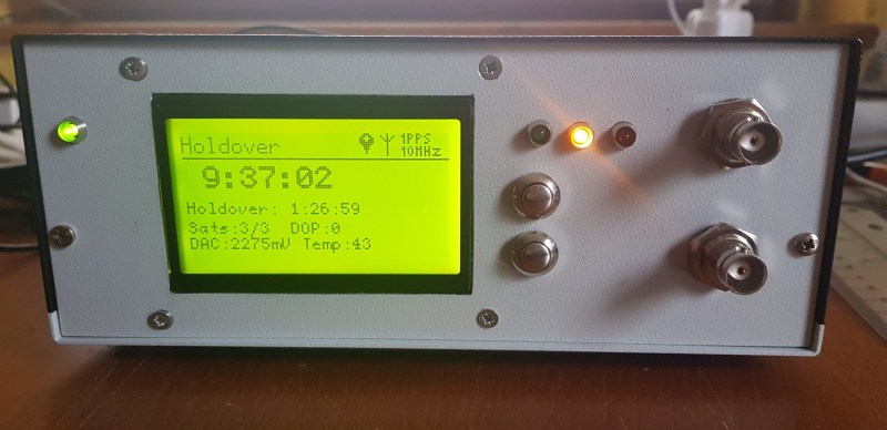
Title: “Reliable Frequency Reference From GPS”. Picture shows: “Holdover” on the screen. So much for: “Reliable”.
Yes, it shows that it is reliable. It could not be called reliable if it would not report holdover when for example reception is lost or any other problem. But instead go silently jettery-jittery.
Does it bother anyone else that they said gps uses triangulation instead of trilateration?