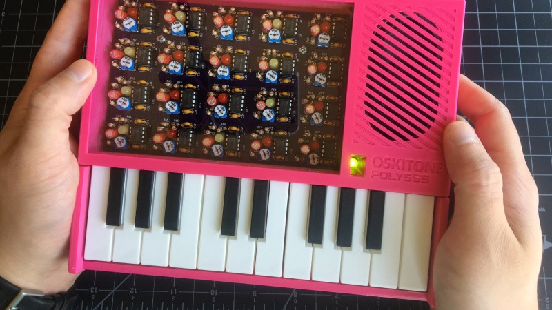
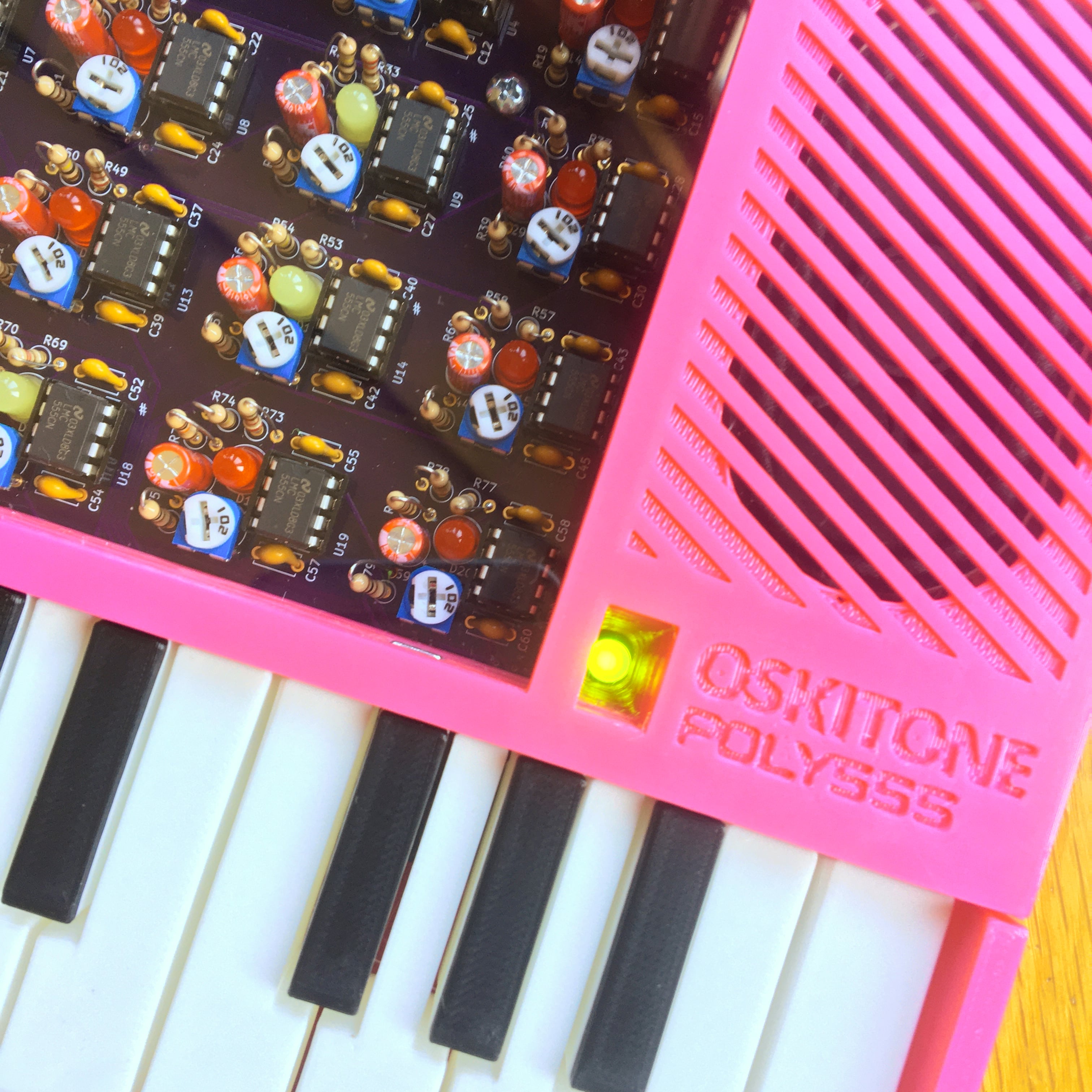
[Tommy]’s POLY555 is an analog, 20-note polyphonic synthesizer that makes heavy use of 3D printing and shows off some clever design. The POLY555, as well as [Tommy]’s earlier synth designs, are based around the 555 timer. But one 555 is one oscillator, which means only one note can be played at a time. To make the POLY555 polyphonic, [Tommy] took things to their logical extreme and simply added multiple 555s, expanding the capabilities while keeping the classic 555 synth heritage.
 The real gem here is [Tommy]’s writeup. In it, he explains the various design choices and improvements that went into the POLY555, not just as an instrument, but as a kit intended to be produced and easy to assemble. Good DFM (Design For Manufacturability) takes time and effort, but pays off big time even for things made in relatively small quantities. Anything that reduces complexity, eliminates steps, or improves reliability is a change worth investigating.
For example, the volume wheel is not a thumbwheel pot. It is actually a 3D-printed piece attached to the same potentiometer that the 555s use for tuning; meaning one less part to keep track of in the bill of materials. It’s all a gold mine of tips for anyone looking at making more than just a handful of something, and a peek into the hard work that goes into designing something to be produced. [Tommy] even has a short section dedicated to abandoned or rejected ideas that didn’t make the cut, which is educational in itself. Want more? Good news! This isn’t the first time we’ve been delighted with [Tommy]’s prototyping and design discussions.
POLY555’s design files (OpenSCAD for enclosure and parts, and KiCad for schematic and PCB) as well as assembly guide are all available on GitHub, and STL files can be found on Thingiverse. [Tommy] sells partial and complete kits as well, so there’s something for everyone’s comfort level. Watch the POLY555 in action in the video, embedded below.


I gotta say it, for fear no one will: Coulda done it with 556’s
if you’re going down that route, why not 558’s ?
The 558 is reduced in functionality compared to the 555 (it’s missing pins for each channel) The 556 is two full 555s on one chip, with nothing but power and ground shared.
558, quad core 555 powah
Technically, he did mention the 556 in his writeup but decided against it.
But this is HAD. 555 one-upsmanship is a requirement.
555’s are so yesterday. Should have done it with nothing but NAND chips.
🤣
Now I’m thinking about a full keyboard and one 555 per key on a bus system in the keys’ spacing… ok… or even one T85 per key? and while idle they could massively parallel calculate mandelbrot set images… mwhuaahaahahahahahahaaaa…
This will be a summer soldering party project for my nieces.
Had fun ordering through hole resistors again instead of SMD (it has been a while)
Rather than lights showing you what voice is being used, some actual controls to change the sound would be nice.
A nice project!
But in no way a “synthesizer” – more a kind of a simple electric organ.
https://en.wikipedia.org/wiki/Synthesizer#Sound_synthesis
Distinction without a difference.
Probably could have done it using an Arduino…
Probably could have done it using a Raspberry Pi…
Or a couple of MO83B1, Top Octave Generator chips.
https://www.ebay.com/itm/SGS-M083-M083B1-MO83B1-Top-Octave-Tone-Pitch-Generator/184563231010?hash=item2af8d36922:g:sTAAAOSwS3pfqWlS
…then add MIDI!
but could it play d_e1m1 ???
It could even play MHALL.
I’ve gone this route a long time ago and I can tell you that frequency stability based on a RC constant is just awful. I’ve build a similar 2 octave synth (I had note tonality as well by mixing with different level of harmonics) and I was spending more time with the synth hooked to a frequency counter and fiddling with the pots that I was playing music.
Can the stability be increased by using higher tolerance components? I assume crystals are the way it’s done in mass production instruments…
It’s not the tolerances (you have a pot anyway), it’s mainly temperature variations and mechanical precision. The ear is very sensitive to frequency ratios. Two semitones are only 6% apart and the human ear can detect ratios as low as 1-2%. The key is to use just one (high frequency) oscillator for all the notes and (fractional) divide that accordingly. The precision of that oscillator is not even relevant because all the notes will shift with it and ratios will be preserved.
>The key is to use just one (high frequency) oscillator for all the notes
It’s not quite that simple. Division from a top octave generator creates exact mathematical ratios, but when you tune a piano for example, the very highest and lowest notes may be tuned up to +-40% high and low from the exact ratio because it makes more pleasing harmonics.
See:
https://en.wikipedia.org/wiki/Stretched_tuning
All good organ oscillators used a quality cap and a coil for independent tone generation, locked phase from top octave chips and dividers aren’t as rich of a sound. The inductor had a slug or rotating ferite shell for tuning. After decades they are still in tune. Some designs can give steady pitch on a variable source of voltage yet have a vibrato LFO voltage input as well.
Were your oscillators always on? I think the POLY555 is helped in that the 555s are off unless their respective keys are held, so there isn’t _too much_ chip-heat-caused frequency drift during regular use. (This is also a big part of why I didn’t go w/ 556s, because they share a VCC pin.)
(Of course, yes, your general point stands — RC designs like this are imperfect. I worked hard to make this one not awful.)
Just a square wave organ. Not a synth.
It’s a synthesizer. And your link in no way provides evidence that it isn’t.
Nice work, thanks for sharing the writeup and source.
Much easier to digest tham a video. I’ve bookmarked it!
Unless you are Thomas Henry, don’t use 555s to produce musical tones. It will end in tears.
A 555 can be used to generate a ramp which can be useful for a lot of sounds , rich n harmonics. A constant current generator makes it a VCO.
PAIA used a unijunction transistor VCO in its first synthesis, and for this purpose a 555 does the same thing.
It was pretty standard at one point, though no specific dates come to mind.
People liked the idea of function generators like the 8038 or 2206, but they had limitations
There are even simpler circuits for generating a straight ramp with a sharp edge, but the benefit of a 555 is that it’s relatively well defined and stable, so the switching hysteresis doesn’t change too much over temperature and frequency.
Take this for example:
http://www.learningaboutelectronics.com/images/Ramp-generator-circuit-with-transistors.png
The left side of the circuit is your constant current generator, and the right side is two BJTs arranged to behave like a thyristor, which triggers whenever the voltage in the capacitor rises above the reference voltage. It dumps the capacitor instantly, and then closes, which resets the ramp.