“You should have used a 555” has become a bit of a meme around these parts lately, and for good reason. There seems to be little that these ubiquitous chips can’t be used for, and in a world where code often substitutes for hardware, it’s easy to point to instances where one could have just used a simple timer chip instead.
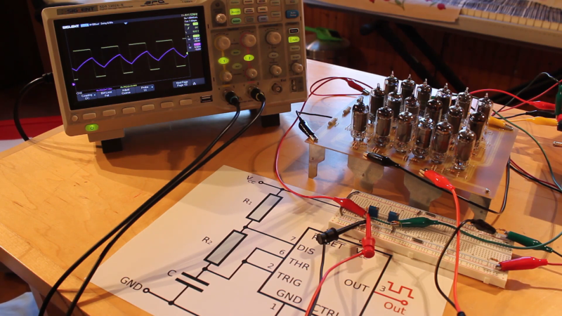
Definitely not in the meme category, though, is this overkill vacuum tube 555 timer. It comes to us via [David Lovett], aka [Usagi Electric], who has lately caught the “hollow state” electronics bug and has been experimenting with all sorts of vacuum tube recreations of circuits we’re far more used to seeing rendered in silicon than glass. The urge to replicate the venerable 555 in nothing but vacuum tubes is understandable, as it uses little more than a pair of comparators and a flip-flop, circuits [David] has already built vacuum tube versions of. The only part left was the discharge transistor; a pentode was enlisted to stand in for that vital function, making the circuit complete.
To physically implement the design, [David] built a large PCB to hold the 18 vacuum tubes and the handful of resistors and capacitors needed. Mounted on eight outsized leads made from sheet steel, the circuit pays homage to the original 8-pin DIP form of the 555. The video below shows the design and build process as well as testing of all the common modes of operation for the timer chip.
You can check out more of our coverage of [David]’s vacuum tube adventures, which started with his reverse-engineering of an old IBM logic module. And while he did a great job explaining the inner workings of the 555, you might want to take a deeper dive into how the venerable chip came to be.


Time to build a vacuum tube Atari punk console
Oooh, now that would be an interesting thing to build indeed!
I think I’ll actually give that a shot once I get closer to getting the kit ready and I have a few completed PCBs in my hands for testing!
Can we get a series started? “Preparing For The EMP” ?
This fits in nicely with the tube 1-bit microprocessor I’m working on too! I’m ready for that blast!
We have a vibrating reed inverter: Hackaday 1026 The Easiest Inverter You Will Ever Make
https://hackaday.com/2021/03/29/the-vibrating-reed-inverter-possibly-the-simplest-inverter-you-can-make/#comment-6335321
That gets you mains & tube voltages. Semiconductors? We don’t need no semiconductors. Where we’re heading, there are no semiconductors.. now where did I put that 0Z4…?
:P
mmm… it missed my comment “Fallout 4 intro music plays here” :P
Last night I pulled out the tube tester and found out the old Wards Airline radio had a funky 12SQ7.
I’ve ordered a replacement from eBay.
The title is too long. “Steampunk 555” would’ve been more on point imho ;-)
Steam might be a tad too old, but “Atompunk 555” sounds perfect!
Now put that thing on the hood of a DeLorean
That would be awesome! Now just to find me a DeLorean…
Should have done it with 12AX7’s (ECC83).
In the series, he determined through very well conducted testing that pentodes are the best for low voltage logic which was a good thing since in the large tube lots he has purchased he has a very large number of them. He even tested a large number of different pentode tube types to see which was the best [largest voltage swings]. Also, because of their audio applications, 12AX7s and several other triodes are way too expensive. He also tested various triodes at the same time he tested the pentodes.
That certainly would have saved some tubes! However, there’s a couple reasons I chose to go with 6AU6 pentodes instead of a dual triode like the 12AX7 (or 6DJ8, 6CG7, etc.).
Firstly, price. 6AU6s can often be found for about $0.30 a tube if buying lots. Even the cheapest dual triodes are near $2.00 a tube and they only go up from there. So, even though I need to use double the amount of tubes, it still comes out to much cheaper.
Next, is low voltage performance. One of the (dumber) things I’ve gotten obsessed with is running tubes with hilariously low plate voltages. For this 555, I’m running just +24V on the plates and -12V for bias. Because I have such low voltages, it becomes really important to pull the plate as low as possible for my logic low values. For the 6AU6, I can get that all the way down to less than 2V for a logic low, but for something like a 12AX7 it’s a lot harder to even just get to 5V.
This has a lot do with the linearity of the triode and the sharp cutoff aspect of the pentode. The transition from cutoff to saturation takes less than 2V difference on the grid for the 6AU6, but in my testing, it takes double that for the 12AX7. This is why the 12AX7 is a fantastic audio tube!
Also, as the tube gets deeper and deeper into saturation, the potential of the plate gets lower and lower. But, the lower the potential of the plate, the less attraction it has for the electrons. Pentodes, on the other hand, have a screen grid tied to VCC, providing essentially an electron accelerator regardless of plate potential. That’s why we can get the plate voltage to super low levels. I’ve even had some pentodes be able to get the plate voltage to less than 0.5V at saturation (the 6AS5 and 6CL6 in particular).
Finally, 18 tubes on a single PCB just looks epic!
Err, this was in reply to ROB, I totally just clicked in the wrong place!
@nakazoto That’s a random “feature” of this blog.
Nice build and video with wonderfull explaning the 555 functions. I always thought that the expression “can also be made with a 555” was some sort of joke as i didn’t know that component :-(
I did grow up in the early beginning of the 74xx series and had some (hobby) projects with tubes what came from old radios and tv sets.
In 2018 i got a part (battery charger with start/stop thresholds) what used the 555 and so i did mis it while i was in the army for 16 months as a heavy rescue driver.
Nice, I just gotta remember, it’s not a bug, it’s a feature!
Thank you for the praise on the video!
The 555 is an interesting chip. At first it seems super limited, but it’s been around for so long and in such huge numbers, the community has come up with some really wild uses for them. There was even someone who made a full adder using just 555 timers, which is insane.
One not-insignificant modern use for 555s is the landmine. Good old 8 pin DIPs. Sobering.
Uniservo: The Lego block is a much better landmine anyway.
This is why I read the HaD comments. The project creator is usually here with great footnotes. Thanks for the explanation.
Thanks for checking the 555 project out!
Regarding your choice of tubes – I think you should still consider ALL the twin triodes out there. There are a whole bunch that are simply going nowhere in the audio world. Extremely slow movers. And if you talk to the tube dealers, you can often pick these tubes up for 25 cents a piece, new in the box (sometimes even less!). Things like any of the tubes in the 6BK7 or 12AV7 line, or even oddball versions of “normal” audio tubes, like 7AU7 or 8CG7. These are such slow movers that the dealers will often value the freed up shelf space over the value of the stock! Ask around. Ignore the listed prices and ask direct about quantity purchases on what we call “the embarrassing glut”.
“6BK7”
Possibly even better, 5BK7A because of the unusual filament voltage. Years ago, doing tube logic experimentation myself, I found that that one had the best price/performance ratio at the time. However, David is working with what he already has the most of in his tube lots.
Useful tip.
I purchased some tiny “grain of wheat” DM160 tubes a while back originally intended as indicators.
Turns out that there are unused internal electrodes that do serve some purpose as the discharge inside changes shape
and brightness.
Alas never found a way to turn them into “magic eye” tubes with the moving bar.
Note: they are *very* fragile and damaged one somewhat during testing but managed to repair it.
The DM-160 is an absolutely gorgeous VFD!
I actually have a handful of the Russian equivalent to the DM-160 (the IV-15) and used those as indicators for the 4-bit vacuum tube instruction register I’m building for my tube computer project: https://youtu.be/5B6whtA_-Ug
This is fantastic!
Slightly off topic, but my elderly father’s pride and joy is his Rogers valve hi-fi audio amp. I can’t believe just how good it sounds. I’ll never listen to an mp3 again and view it as hi-fi. However, he’s looking for spare Mullard valves for it, which I understand are super hard to get hold of. Any ideas from the experienced ladies and gentlemen who read Hack a Day, about where he could source these, would be appreciated! (I don’t have the exact amp model and valve part numbers right now)
It’s a Rogers E20a amplifier. Valves are:
Input: 12AX7
Gain: 6SN7
Output: 6L6G or GC
Check out the audiophile forums they “trusted” places to buy tubes and will be able to give you better opinions on “equivalent” tubes.
Tube rolling guides (swapping for equivalents) are popular I don’t buy into significant audio differences unless the tubes are not genuinely equivalent.
eBay has plenty of tubes in every condition, from used, to NOS, to Slovak gold-plated, to Mullard :)
Thank you!
As Alex said, check out the HiFi audio groups and Tube Roller groups. They often know great sources for tubes.
Useful info! Thanks to those that responded.
Pff. I could have done that with a couple of 555’s..
I’ts 555 all the way down…
How many 555s does it take to make a 555?
Five!
One to loose in the fluffy carpet.
Another to be soldered in the wrong way around.
The third one to release the magic smoke because of a too high output current(?).
The fourth to vanish in another project.
And finally the remaining one actually does what it was intended to do.
;-)
that is eerily accurate
Neodawg has a 555 chip, Jacks chip makes him blink a lot
This reminds me of the computer Spock built in the 1930s (or was it 20s? Damn I should watch TOS again) to read out his tricorder.
I am attempting to construct a 555 timer using stone knives and bearskins.
Well good luck getting your platinum, Edith.
“Dammit Jim! I’m a doctor, not an actor! Uh… wait…”
I don’t know if I’ve seen that episode,but I have seen some screenshots of Spock’s computer. Interestingly, it looks like he’s using old school octal based power pentodes. And only 10 of them at that! There’s not a whole lot of computing you could do with 10 tubes, but, if they were dual triodes instead, he could build a bit-serial full adder at least!
Didn’t know that you can still get new vacuum tubes.
Or are they all second hand 60 year old ones that still work ?
These are all used tubes I bought in large lots off eBay. Tubes are surprisingly resilient, especially the later 7-pin tubes from the 50s and 60s. Of the thousand plus tubes I have, I’ve only had a handful go bad, and those were primarily broken glass from dropping them.
https://static.wikia.nocookie.net/bttf/images/0/04/TimeControlTubesModel.jpg/revision/latest/scale-to-width-down/640?cb=20080802225029
https://backtothefuture.fandom.com/wiki/DeLorean_time_machine?file=TimeControlTubesModel.jpg
This link
I’m really curious what it’s based on! I wonder if it’s a modified tube radio for some movie magic?
Poor David, Already sold dozen’s off them and he hasn’t even’t considered making the kits yet!
Common david we all want to make one of these!
Haha, you’re telling me! I’ve been working on the OpAmp design, trying to both get the tube count down as well as make it universal enough to work with multiple different tubes. So far, I’ve got it down to 4 pentodes per OpAmp and working with both a 6AU6 and 6CB6, and all that is required is a little adjustment of some potentiometers. Hopefully, this will make it much more flexible for people to run different tubes in the design.
I’m having a much harder time getting it to work with dual triodes, so in the end, it may end up as just being a small pentode only kit. I’ve been working on finding a good source for sockets as well as trying to figure out a good way to do the legs for that extra large DIP look. I’m getting pretty close to designs I’m happy with, so it’s about time to start ordering parts for the first prototype kits!
Did you test the frequency response from it ? How high and low can you push it ?
I did some limited testing in Astable mode to see what kind of frequencies I can push. I’ve had it down to about 2 Hz, which is great for flashing a little VFD. It might be able to go lower, but things were getting a little unstable at that slow of a speed, so I’m not sure how much.
I also did some high speed testing and around 8kHz is about as fast as you can reasonably take it. Any faster than that and the falling edge starts to fall too slow. You can see that in action here: https://i.postimg.cc/fRBJ9Nx6/IMAG3517.jpg
This is most likely due to the incredibly low voltage I’m running, but I’m not sure why we don’t see that same curve on the rising edge. I may have to do a bit more probing to see if it’s a problem with my buffers or my SR Flip Flop.
Either way, for what it is, I’m pretty happy with the level of flexibility it has!
Since nobody else has done it…
“Hey, where’s the Arduino…?” :P
Also: pffffft. Diode-resistor logic, with a neon-lamp oscillator circuit, would have been far more than sufficient here. Why even bother faffing about with electronic valves in the first place…?
For those of insufficient mental acuity (and, thus, overbearing obtuseness of the mind) — obviously, that was a joke comment post.
Back in tech school, my instructor had a 400 Hz hollow state oscillator he asked me to troubleshoot.
After a short time the output tubes[valves] would get cherry red and it was time to shut it off before they blew.
I never did figure out what the problem was. I recall borrowing as many 260 VOMs as I could get from my lab mates to monitor various voltages…
faire attention au courant de plaque (anode)
Pay attention to the plate current (anode)
So when is glasslinger going to put all of this in one tube?
Ah you beat me to it, that is exactly what I was wondering!
This raises the obvious question of if a single custom vacuum tube could contain all of the functionally of a 555. Were integrated vacuum tube circuits ever a thing?
Simple answer: yes, they were a thing. See for example the dekatron.
https://en.wikipedia.org/wiki/Dekatron
Was a 2D21 thyratron tube considered as a possible starting point?
Not to criticize this design – it is quite a nice job. But I worked in the vacuum tube era, time shifted forward because I was working on military equipment older than myself, in many cases. With transistors, the parts are so cheap, you can use as many as you like, and with integrated circuits this just got worse, or better, depending on how you look at it. But with tubes, there was a significant cost savings when you could remove a tube from a design. Which is why it is possible to make a superheterodyne receiver from just five tubes, and that’s with one of them just being used as a rectifier. For the superhet, the pentagrid converter was invented. This was a single-tube circuit that functioned as an oscillator and a mixer, all in one. But specifically for the case of making multivibrators, there was a single pentode circuit called (no lie) a phantastron, that managed to be bistable, and usable as a flip-flop. Yeah. Furthermore, the comparators needed for a 555 wouldn’t need to have as much gain as a full-fledged operational amplifier, so you could probably save a couple of tubes there.
On the other hand, “I coulda’ done it with eighteen vacuum tubes” is absolutely the best way to go when you have unlimited budget.
I remember almost fifty years ago people complaining that they didn’t like ICs because they were too complicated, and gave seen similar comments in recent years. At least in the seventies they were people who grew up with tubes.
You often don’t need to know what’s inside. An opamp is a gain block.
But if you look at the internal schematic, there almost always are “extra parts”. Some of it’s because it costs nothing, but gives a nore stable design. Some of it is to get around using some parts, which are either hard to implement or impossible.
I remember a sweep generator that basically used opamps to build a 555 equivalent, it allowed more versatility. But generally, you’d use something else in tube days. It would be specific to the need, rather than a general purpose circuit. So a neon bulb relaxation oscillator would do a lot of the work. And something else if you needed a long pause. All kinds of timing went on in tube days, and nobidy said “a 555 will do”
The 555 is a bunch of often used circuit elements packaged together. It’s almost the minimum set of functional blocks you need for a generic timing task. Of course you can implement those functions otherwise – a basic relaxation oscillator takes exactly one tube or a single thyristor – but what you don’t get is things like the improved thermal stability that comes with using comparators instead of the inherent properties of the component for your trigger points. The behavior of a 555 is more predictable and robust than the simpler circuits.
One of the things you could improve is to have a second control input to set the low end of the hysteresis range, but then it wouldn’t fit in an 8-DIP.
I may have missed a comment addressing this point as I didn’t fully read every comment, but as the 555 is a hybrid chip containing Digital and analog circuitry would this still be considered a hybrid?
The flip-flops are made from transistors and the op-amps and output drive are made from transistors to along with some resistors.
So it’s technically not a hybrid IC.
The terms “analog” and “digital” are not actually opposed or complementary terms. They relate to different things.
A digital TV transmission travels through the air as an analog signal modulated by a digital protocol.
Analog is a “method” of operation that is defined by the common laws of physics.
Digital is a “mode” of operation that can be a mode of analog electronics right through to a mode of marbles and bits of wood.