Placing two motors together in a shared drive is a simple enough task. By using something like a chain or a belt to couple them, or even placing them on the same shaft, the torque can be effectively doubled without too much hassle. But finding a way to keep the torque the same while adding the speeds of the motors, rather than the torques, is a little bit more complicated. [Levi Janssen] takes us through his prototype gearbox that attempts to do just that, although not everything works exactly as he predicts.
The prototype is based on the same principles as a differential, but reverses the direction of power flow. In something like a car, a single input from a driveshaft is sent to two output shafts that can vary in speed. In this differential drive, two input shafts at varying speeds drive a single output shaft that has a speed that is the sum of the two input speeds. Not only would this allow for higher output speeds than either of the two motors but in theory it could allow for arbitrarily fine speed control by spinning the two motors in opposite directions.
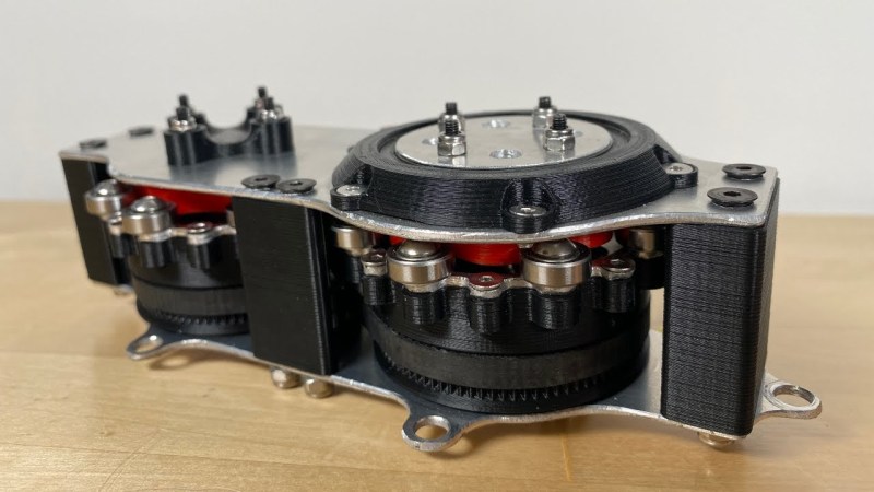
The first design uses two BLDC motors coupled to their own cycloidal drives. Each motor is placed in a housing which can rotate, and the housings are coupled to each other with a belt. This allows the secondary motor to spin the housing of the primary motor without impacting the actual speed that the primary motor is spinning. It’s all a lot to take in, but watching the video once (or twice) definitely helps to wrap one’s mind around it.
The tests of the drive didn’t go quite as planned when [Levi] got around to measuring the stall torque. It turns out that torque can’t be summed in the way he was expecting, although the drive is still able to increase the speed higher than either of the two motors. It still has some limited uses though as he notes in the video, but didn’t meet all of his expectations. It’s still an interesting build and great proof-of-concept otherwise though, and if you’re not clear on some of the design choices he made there are some other builds out there that take deep dives into cycloidal gearing or even a teardown of a standard automotive differential.
Thanks to [Kelvin Ly] for the tip!


i coulda toldja that! but it is awesome that his fabrication skills (and the general state of the art of fabrication) are at the point where it’s possible to learn that directly by making prototypes!
I’m waiting for the moment someone replicates/builds a Toyota Power Split device with two electric and one combustion motor and is able to demonstrate fuel efficiency…
Even starting from known ratios – this would be a serious diy project building mechanics, motor management and overall control circuitry.
This was my first thought too. The Toyota PSD has two leccy motors and the ICE all linked to a planetary gearbox.
The ICE is on the sun gear with the leccy motor on the planet carrier acting as a clutch. By spinning opposite to the ICE the carrier motor effectively disengages the ICE and prevents it stalling. The other motor is on the main ring gear and drives the wheels directly. So you can get torque multiplication of the ICE with the motor running slower than ICE but you can also geat input speed addition if the carrier motor stops.
It’s a pretty impressive system
I’m fairly sure you can’t increase the speed *and* torque by using two motors – it’s one or the other (or, ok, some ratio of the two). But also this method seems a complex and lossy way to get higher speed. Wouldn’t it be better to sum the torque and then use a gearbox to convert the increased torque to increased speed?
Though I suppose this design might avoid RPM limits on bearings by having no single bearing rotating at full speed. That itself is quite interesting.
Yes. This is just a very convoluted 2:1 gearbox.
I had thought about this several years ago as a type of torque converter for a low speed loader. by using two engines powering each other through a diff you could go forward or backward by revving one engine higher than the other. it would be very inefficient and the slower revving engine would be inclined to stall.
There was a company in the early to mid 2000s that offered a very similar, if not the same, principle for an electric propulsion system for sailboats and small sized catamarans using a battery bank instead of an internal combustion engine… They called it the “electric wheel” or something similar, and they claimed high performance as a generator while under sail and high torque even at low rotation speeds. The motor sizes were made to replace 5-25 HP inboard/ outboard motors. Having no money at the time I wasn’t able to buy one for testing. Not sure if the company still exists today. If memory serves me correctly they also had longer physical versions of the motor that had additional control over a second and or third outer gear. Motors windings directly drove the rotor gears with no belts required.
Note that having a “differential” is not equivalent to “differential drive” which normally refers to “skid steering”…
May need to watch that Vid a few more times, but if I am understanding right and it would probably take alot of code rejig but if the two motors /mechanism have distant advantage of variable speed then in 3D printing circles and curves could potentially be done without any notable stepper motor step errors in the x and z transitioning in and out of X & Z e.g. x slows and z increases inline with 1st 1/4 of curve requirements then z slows and reverse direction of x increases for 2nd 1/4 etc et so and so forth for a circle for continuous smooth printing over stepped positioning prints. hmmmm