
We are always impressed with something so simple can actually be so complex. For example, what would you think goes into an analog computer? Of course, a “real” analog computer has opamps that can do logarithms, square roots, multiply, and divide. But would it surprise you that you can make an analog device like a slide rule using a Wheatstone bridge — essentially two voltage dividers. You don’t even need any active devices at all. It is an old idea and one that used to show up in electronic magazines now and again. I’ll show you how they work and simulate the device so you don’t have to build it unless you just want to.
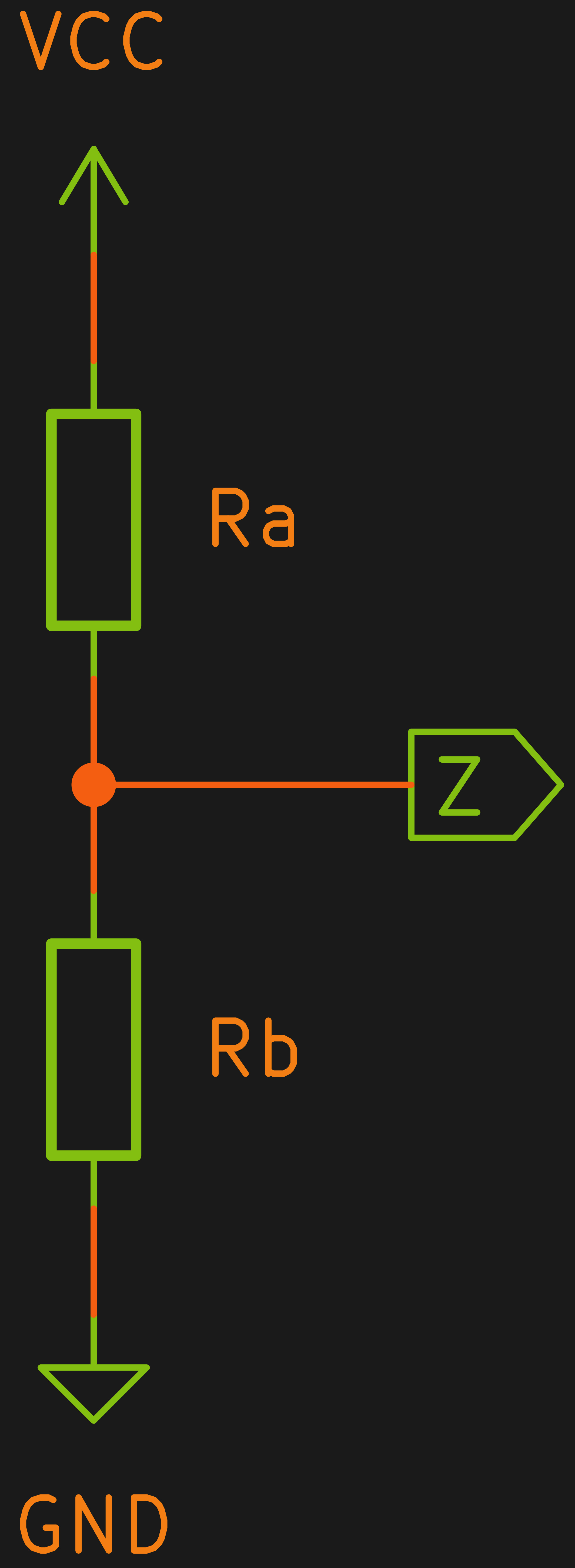 A voltage divider is one of the easiest circuits in the world to analyze. Consider two resistors Ra and Rb in series. Voltage comes in at the top of Ra and the bottom of Rb is grounded. The node connecting Ra and Rb — let’s call it Z — is what we’ll consider the output.
Let’s say we have a 10 V battery feeding A and a perfect voltmeter that doesn’t load the circuit connected to Z. By Kirchoff’s current law we know the current through Ra and Rb must be the same. After all, there’s nowhere else for it to go. We also know the voltage drop across Ra plus the voltage drop across Rb must equal to 10 V. Kirchoff, conservation of energy, whatever you want to call it. Let’s call these quantities I, Va, and Vb.
There are many ways to go from here, but let’s accept that the current through two series resistors will be the same as if it were one resistor of equal value. That is, a 1 KΩ and a 2 KΩ resistor in series will draw as much current as a 3 KΩ resistor. That means Ohm’s law tells us:
I = 10/(Ra+Rb)
Now you can solve for each voltage drop:
Va = I Ra

Vb = I Rb
In fact, our voltmeter at Z will measure Vb since it is grounded.
Big Hairy Deal
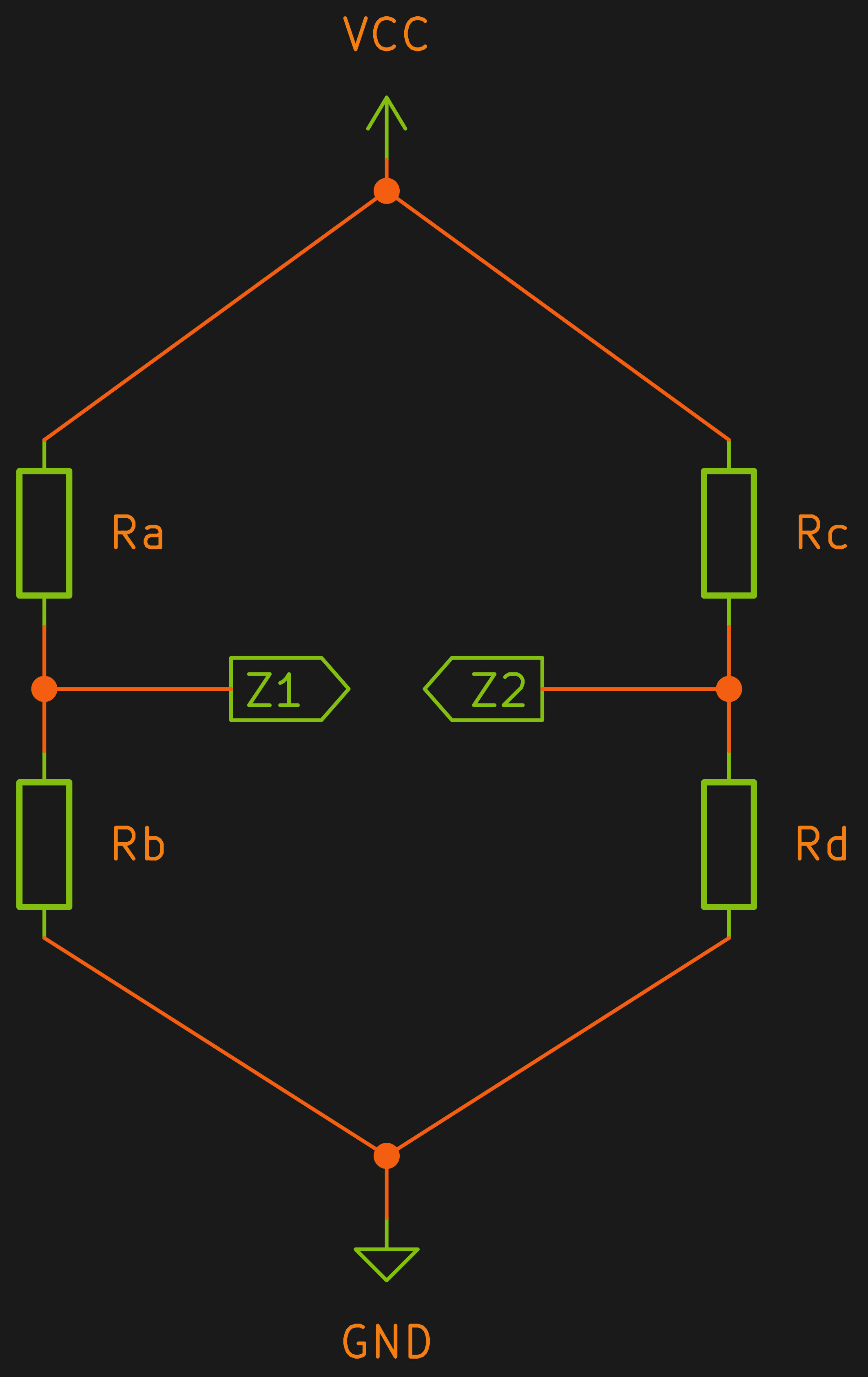 Of course, you probably know about voltage dividers. But we were going to talk about Wheatstone bridges. The truth is these are just two voltage dividers in parallel and you measure the voltage between the two outputs (call them Z1 and Z2). You often see this circuit drawn like a diamond, but don’t let that fool you. It is still just two voltage dividers.
Without using any math, you can see that if the voltage dividers are the same then Z1 and Z2 will be the same and, therefore, no current will flow because the voltage between the two points is zero. What happens when the divider is not the same? There will be more voltage on one Z point than the other.
Historically, this was used to measure resistance. You could use two matched resistors in part of the bridge, have an unknown resistance in one of the remaining legs and a variable resistor with a dial calibrated to read ohms. You’d turn the dial until a meter read zero and read the resistance value from the dial. If the power source is AC, you can also measure reactance using a similar circuit.
But the Slide Rule?
So how do you get from a piece of antique test equipment to a slide rule? Let’s change the bridge so the left-hand divider has resistors Ra and Rb while the other one has Rc and Rd. We can look at the algebra:
Z1=V (Rb/(Ra + Rb))

Z2=V (Rd/(Rc + Rd))
We want Z1 to equal Z2 so:
V (Rb/(Ra + Rb)) = V (Rd/(Rc + Rd))
We can divide both sides by V and get rid of that term:
(Rb/(Ra + Rb)) = (Rd/(Rc + Rd))
So to balance the bridge we need:
(Ra + Rb)/Rb  = (Rc + Rd)/Rd    reciprocal both sides

(Ra Rd + Rb Rd) = (Rc Rb + Rb Rd)    multiply both sides by Rb Rd

Ra Rd = Rc Rb      subtract Rb Rd from both sides

Ra = (Rb Rc)/Rd    Solve for Ra
As a simple thought experiment, then, imagine that Rd=1. If you set Rb and Rc then you can adjust Ra to balance and the value of Ra will be the answer. Or you can set Rb to 1 and enter numbers in Rc and Rd. Once you balance Ra, you’ll know the result of the division.
In practice, though, you might want to scale the result, especially for division. For example, if Rb=1, Rc=2, and Rd=1000 you would need to set A to .002 ohms which is hard to do. In that case, though, you could set Rb to a scale factor. If it were, say, 10K, then Ra can be set to 20 ohms.
Simulation
You could break out a few potentiometers and have a go at this. We’d suggest linear ones unless you are very handy at making logarithmic scale dials. But since this is Circuit VR, we’d rather do a simulation. Falstad fits the bill, but any simulator is well up to the task.
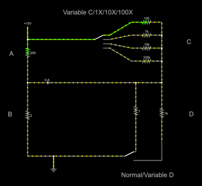
There are two switches in the simulation. The top “C” switch lets you switch in the top resistor or a 10X, 100X, or 1000X range resistor for C. The bottom “D” switch lets you select a 1 ohm resistor or a variable resistor for D. The ammeter in the center shows the bridge balance and will read 0A when you are in balance.
Speaking of variable resistors, I did put sliders for each of the resistors on the right sidebar of the simulator. However, using them often puts values in like 10.002K which reads 10K on the screen and is a source of error. Of course, you’d have the same problem with real pots, so maybe that’s a good simulation. However, it is better to double click the resistor you want to change and enter its value directly. Obviously, you shouldn’t change the three fixed C resistors or the fixed D resistor.
Next Steps
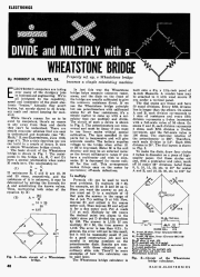
If you want to see what this circuit looked like in the flesh, check out pages 48 and 49 of the June 1960 Radio Electronics. It may have even been the very article that spawned [Bil Herd’s] first computer kit. A similar kit from Edmund Scientific used three potentiometers to form the bridge in a common configuration. We’ve even seen a version from GE that used an audio oscillator so you could hear the null point using headphones. You can see both of those on the article starting on page 65 of the December 1961 Popular Electronics. Or check out a newer build over on Hackaday.io.
It would be an easy enough rainy day project. If you have an old-fashioned mirror scale meter from an old multimeter, it would really shine in this application. Making the dials in a CAD program and printing them out would be effortless, too.
If you want a challenge, why not use an AC source along with variable capacitors and inductors to make a complex number calculator? That’d be something and if you pull it off, we’d cover it.
Meanwhile, we’d like to point out that real analog computers were not this simple. On the other hand, by definition, this is an analog computer just like a real slide rule. If you read the Radio Electronics article, you’ll see it can even chain an answer into the next problem just like you would do on a slipstick.


Great article and what a fun concept! Adding it to my list…
Another one here:
http://www.arthropodsystems.com/AnalogComputer/AnalogComputer1.html
I once worked for a place that built tension transducers and discovered that as a quick demonstration one could make a simple load cell with just a piece of paper and a #2 pencil. Draw a squared off U shape “|_|”. Make one left wider. Make all lines thicc af boi. Attach multimeter clips to tips of U. Set multimeter to ohms. Curling paper towards drawn side decreases resistance and curling the other way increases it.
Similar schemes were used for grid-leak resistors in 1920s. Megaohm range I believe. What is the range of resistance you got with that setup?
It was highly variable depending on trace widths, trace thicknesses, even the brand of pencil seemed to make some difference tho this is anecdotal at best. If memory serves I want to say that those sensors would swing from around 1.5MOhms up to about 5MOhms.
Great article, Al! Thank you!
I made a list of several of these with my own implementation here: https://hackaday.io/project/177346-simple-analog-computer-electronic-slide-rule
The 2008 plans look good to me. I am looking at the 3590S 10k multi-turn Precision Potentiometer on Aliexpress.com. For $14 including tax and shipping you get:
2 50k
2 10k
1 5k
1 1k
3 of the 10 turn dial knobs
I figure you get some choice 50/5K or 10/1K and can always use the spare in another project (modding power supplies or overvolting video cards?)
Also thinking of using the LM317 current limiting power supply from the https://hackaday.com/2022/03/10/short-circuit-tracer-for-a-buck/ article to keep the power consumption low and save the Ammeter XD.
Also, if you only wanted 3 pots and their knobs, under $10 (before their $4 sign up coupon)
Not shilling, just a happy customer
It’s nice there are archives of such source material.
Enjoyable read.Thanks.
I was always fascinated by electronic analog computers. AFAIK analog computer IC’s usually use bipolar transistors to do multiplication and division, based on the fact that the voltage across a diode is logarithmically proportional to the current through it, so very much like a classic slide rule. Here is one example:
https://www.analog.com/en/products/ad539.html
Veritassium recently did a piece on analog computers and how they might be a good match for AI:
https://www.veritasium.com/videos/2021/12/21/the-most-powerful-computers-youve-never-heard-of
The most advantageous aspect of the Wheatstone bridge is that you can add a multiplayer effect.
The circuit only determined if the resistance ratio of side A is the same as the resistance ratio of side B.
You can for example use a 1k potentiometer that is perhaps 10 turn and has decade markings so that it reads from 10 to 1000 ohms in marked increments of 10 ohms. On the other half of the side you could switch 10 Ohm, 100 Ohm, 1k, 10k, 100k to get multiple decades of measurement with at least 2 digit accuracy Most e12 (and now e24) resistors are two digit anyway.
Probably more important in the digital era is the Wien bridge that works on exactly the same principle except that an AC voltage is applied to you can measure reactive components (capacitors / inductors) as well as resistors.
Furthermore the Wien bridge can be set up as an oscillator where you have a selectable frequency multiplier and a fine control (pot) or have a fixed frequency output that has high frequency stability.
The May 1955 issue of Popular Electronics detailed a build-it-yourself lie detector using a 3S4 amplifier and a Wheatstone Bridge to measure resistance between fingers on opposite hands. I made one in high school and used it to detect whether the subject lied when asked to secretly pick a digit from 0 to 9 and then reply no to randomly selected digits by the operator. It was perfect in detecting the “secret” digit, which, by the way, was more often than not, 7. It required a VTVM (Vacuum Tube Volt Meter) and a Heathkit VM-7 worked great. What a cool way to show an application of simple circuits!